
MEMS microphone acoustic structure

An acoustic structure and microphone technology, applied in the field of microphones, can solve the problems of MEMS microphone acoustic structure limitations, uneven frequency response, etc., and achieve the effect of suppressing high-frequency warping and being easy to implement

Inactive Publication Date: 2015-09-09
ZILLTEK TECH SHANGHAI +1
View PDF7 Cites 0 Cited by
  • Summary
  • Abstract
  • Description
  • Claims
  • Application Information

AI Technical Summary

Problems solved by technology

[0002] With the development of mobile multimedia technology, people's requirements for voice quality are getting higher and higher. In the design of sound transmission, MEMS (Micro Electro Mechanical System Microphone, microelectromechanical system microphone) microphone technology has the advantages of Thin and small size, high reliability, high temperature resistance and other excellent features make it widely used. However, when the existing MEMS microphone structure is in use, the sound signal enters the microphone acoustic cavity after diffracting once through the acoustic through hole, that is, it is received by the microphone. The transducer inside the acoustic cavity realizes electrical output after receiving. The above-mentioned acoustic structure adopts a first-order acoustic model, and its frequency response is not flat and there is high-frequency warping. For applications that want to obtain a flat frequency response, the prior art Acoustic structure of MEMS microphones is limited

Method used


Image

  • MEMS microphone acoustic structure
  • MEMS microphone acoustic structure

Examples


Embodiment Construction

[0020] The following will clearly and completely describe the technical solutions in the embodiments of the present invention with reference to the accompanying drawings in the embodiments of the present invention. Obviously, the described embodiments are only some, not all, embodiments of the present invention. Based on the embodiments of the present invention, all other embodiments obtained by persons of ordinary skill in the art without creative efforts fall within the protection scope of the present invention.

[0021] It should be noted that, in the case of no conflict, the embodiments of the present invention and the features in the embodiments can be combined with each other.

[0022] The present invention will be further described below in conjunction with the accompanying drawings and specific embodiments, but not as a limitation of the present invention.

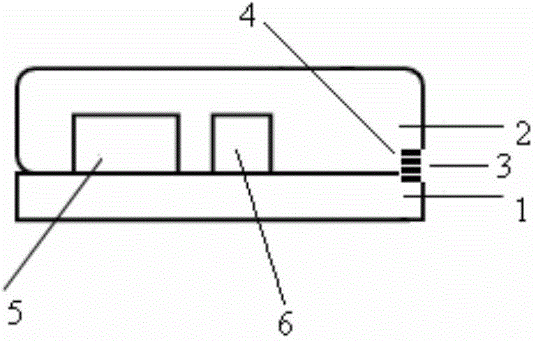
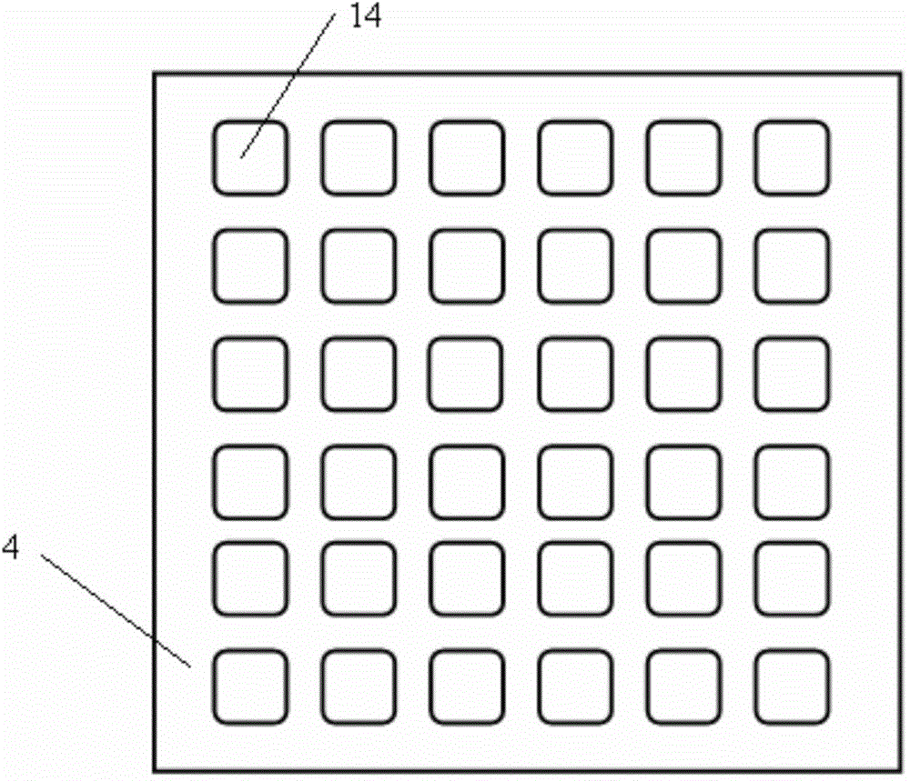
[0023] refer to figure 1 , a MEMS microphone acoustic structure, comprising a first layer structure 1 and a sec...


PUM


Abstract

The invention relates to the technical field of voice processing equipment and specifically to a microphone. A MEMS microphone acoustic structure comprises a first layer structure and a second layer structure on the first layer structure. The first layer structure and the second layer structure constitute a microphone acoustic cavity. The microphone acoustic cavity is equipped with a first acoustic through hole used for acquiring an acoustical signal. An acoustic member is arranged in the microphone acoustic cavity and is provided with at least two second acoustic through holes. On the basis of available technology, the MEMS microphone acoustic structure processes the acoustical signal for the second time so as to effectively inhibit high-frequency warping and obtain a flat frequency response. Further, the volume of a single microphone is not changed such that a peripheral sound guiding rubber sleeve is not required to be changed. The MEMS microphone acoustic structure is easy to produce.

Description

technical field [0001] The invention relates to the technical field of voice processing equipment, in particular to a microphone. Background technique [0002] With the development of mobile multimedia technology, people's requirements for voice quality are getting higher and higher. In the design of sound transmission, MEMS (Micro Electro Mechanical System Microphone, microelectromechanical system microphone) microphone technology has the advantages of Thin and small size, high reliability, high temperature resistance and other excellent features can be widely used. However, when the existing MEMS microphone structure is in use, the sound signal enters the microphone acoustic cavity after diffracting once through the acoustic through hole, that is, it is received by the microphone. The transducer inside the acoustic cavity realizes electrical output after receiving. The above-mentioned acoustic structure adopts a first-order acoustic model, and its frequency response is not...

Claims


Application Information

Patent Timeline
Patent Type & Authority Applications(China)
IPC IPC(8): H04R19/04
Inventor 叶菁华
Owner ZILLTEK TECH SHANGHAI
Learn More