
CPCI printed board test case

A technology for testing chassis and printed boards, used in printed circuit testing, electronic circuit testing, electrical measurement, etc., can solve problems such as increased workload, inaccurate positioning, reduced work efficiency, etc. Time, the structure of the chassis is simple, and the effect of improving work efficiency

Inactive Publication Date: 2020-01-07
TIANJIN EMBEDTEC
View PDF6 Cites 0 Cited by
  • Summary
  • Abstract
  • Description
  • Claims
  • Application Information

AI Technical Summary

Problems solved by technology

[0003] The inconvenience caused by these two test methods is that the force on the board is uneven and the positioning is not accurate during the process of manually inserting the board into the bottom plate slot, and the long-term insertion and removal will affect the pin insertion.
Moreover, it is laborious to pull out the printed board from the slot of the bottom plate, and if the force is too strong, it will cause damage to the electrical components on the printed board.
The method of processing cold boards needs to process different cold boards for different printed boards, which will first increase the cost, and secondly fix the cold boards with screws, requiring frequent installation and removal of screws, increasing the workload, which will Delay the test time of printed boards and reduce work efficiency

Method used


Image

  • CPCI printed board test case
  • CPCI printed board test case
  • CPCI printed board test case

Examples


Embodiment Construction

[0024] The present invention will be further described in detail through the accompanying drawings and specific embodiments below.

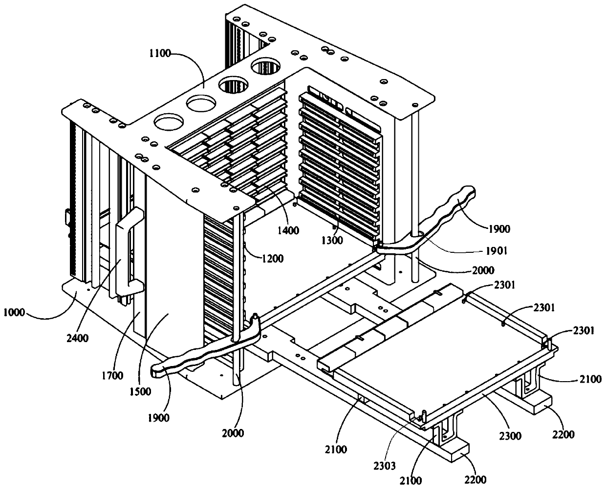
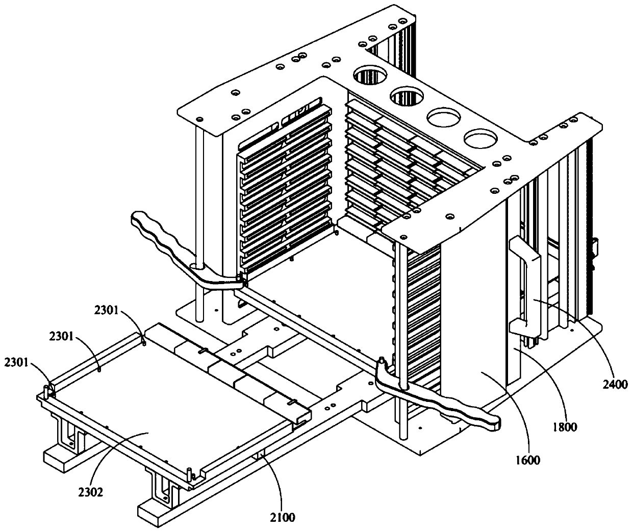
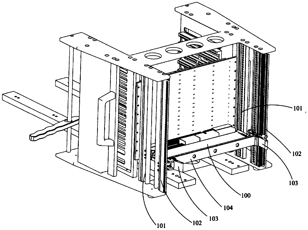
[0025] Such as Figure 1-3 A kind of CPCI printed board test case shown, comprises frame, the CPCI bottom plate printed board 1400 that is vertically arranged in the frame, and the CPCI bottom plate printed board divides the frame into a front board installation area and a rear side In the wiring area, the rack includes a bottom plate 1000, a top plate 1100, and a left side plate 1200 and a right side plate 1300 arranged on both sides of the installation area and connecting the bottom plate and the top plate; a structural cold plate is arranged in front of the installation area 2300, the bottom of the cold plate of the structural part is connected with a pair of linear guide rails, the linear guide rails are arranged on the bottom plate, and the cold plate of the structural part can slide into the installation area on the linear guide rails.

[...


PUM


Abstract

The invention discloses a CPCI printed board test case, which comprises a rack and a CPCI backplane printed board, wherein the CPCI backplane printed board is vertically arranged in the rack and divides the rack into a front board installation area and a rear routing area; the rack comprises a bottom plate, a top plate, a left side plate and a right side plate; the left side plate and the right side plate are arranged at two sides of the board installation area and are connected to the bottom plate and the top plate; a structural member cooling plate is arranged in the front of the board installation area; the bottom of the structural member cooling plate is connected with a pair of linear guide rails; the linear guide rails are arranged on the bottom plate; and the structural member cooling plate can slide into the installation area on the linear guide rails. The CPCI printed board test case has the advantages and beneficial effects that the case is simple in structure and easy to operate, and flexible insertion and extraction can be achieved only by lightly putting the to-be-tested printed board into the structural member cooling plate and rotating handles, so that the assembly time of the printed board is shortened, accurate positioning can be achieved, the stress is uniformly distributed, the work efficiency can be greatly improved and the work accuracy is improved.

Description

technical field [0001] The invention relates to the field of CPCI equipment, in particular to a CPCI printed board test case. Background technique [0002] At present, there are many units in our country that produce and operate military products such as hardened computers and boards. Each unit develops boards with various functions every year to meet customer needs. It is necessary to test the boards developed by ourselves, and they can be delivered to customers if they pass the test. At present, these boards are tested by manually inserting them directly into the standard backplane for testing, and the second is to fix the printed board on the cold plate with screws. The cold plate was then tested by inserting it into a chassis with standard backplane slots. [0003] The inconvenience caused by these two test methods is that the board card is not uniformly stressed during the process of manually inserting the board card into the slot of the bottom plate, the positioning i...

Claims


Application Information

Patent Timeline
Patent Type & Authority Applications(China)
IPC IPC(8): G01R31/28G01R1/04
CPCG01R1/04G01R31/2806G01R31/2808
Inventor 赵磊
Owner TIANJIN EMBEDTEC
Learn More