
Multi-factor flame recognition method suitable for embedded platform

A flame recognition and multi-factor technology, applied to character and pattern recognition, fire alarms that rely on radiation, fire alarms, etc., can solve problems such as low robustness, unable to express fire information normally, and long detection time , so as to avoid the huge amount of calculation, increase the scope of detection, and facilitate the investigation and evidence collection

Active Publication Date: 2020-01-03
SOUTH CHINA NORMAL UNIVERSITY
View PDF10 Cites 7 Cited by
  • Summary
  • Abstract
  • Description
  • Claims
  • Application Information

AI Technical Summary

Problems solved by technology

[0002] At present, there are three mainstream methods for fire identification. The first method uses traditional fire detection sensors to detect fire information, which generally has the disadvantage of long detection time and low accuracy.
The second is to use image recognition to detect fire information, that is, to use traditional digital image processing methods to manually set the feature dimension of fire for fire identification, that is, to manually design multiple representative features to represent fire information. However, due to the limited characteristics of artificial fire representation, fire information in different scenes or different backgrounds cannot be expressed normally, and there are generally disadvantages of high misjudgment rate and low robustness.
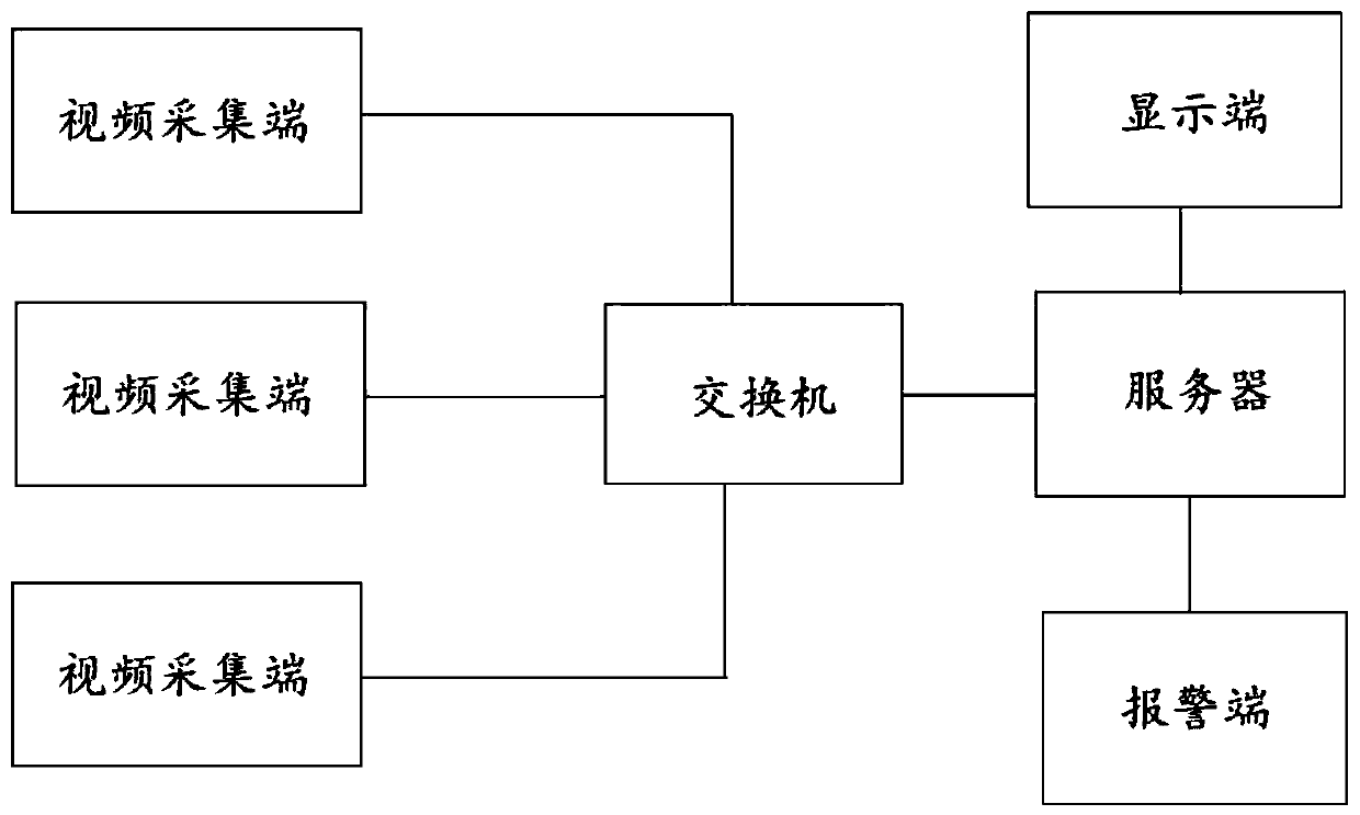
like figure 1 As shown, it is a diagram of a traditional fire identification system. When a general-purpose deep learning method is used for fire identification, the on-site video collected by multiple video acquisition terminals is transmitted to the background server through the switch, and the background server performs centralized calculation, resulting in calculation Huge amount

Method used


Image

  • Multi-factor flame recognition method suitable for embedded platform
  • Multi-factor flame recognition method suitable for embedded platform
  • Multi-factor flame recognition method suitable for embedded platform

Examples


Embodiment Construction

[0033] A number of implementations of the present application will be disclosed in the following figures. For the sake of clarity, many practical details will be described together in the following description. It should be understood, however, that these practical details should not be used to limit the application. That is to say, in some embodiments of the present application, these practical details are unnecessary. In addition, for the sake of simplifying the drawings, some well-known and commonly used structures and components will be shown in a simple schematic manner in the drawings.

[0034] In addition, in this application, the descriptions involving "first", "second" and so on are only for the purpose of description, not specifically referring to the sequence or order, nor are they used to limit the application, but only for the purpose of distinguishing the following The components or operations described by the same technical terms are only used, but should not b...


PUM


Abstract

The invention discloses a multi-factor flame recognition method suitable for an embedded platform. The method comprises the steps of building a fire sample library, wherein the fire sample library isfrom a network fire picture and a combustion experiment picture; obtaining a plurality of live video frames separately; extracting moving objects in each live video frame separately and obtaining oneor more quasi-fire areas; carrying out fire confirmation on one or more quasi-fire areas according to the fire sample library and judging whether fire information exists in the one or more quasi-fireareas or not; and if so, carrying out fire classification on the fire information and generating corresponding alarm signals according to the classified fire classes. According to the multi-factor flame recognition method, the obtained live video frames are processed separately, whether the fire information which can be developed into a fire appears or not in a live monitoring environment is analyzed in real time, fire confirmation is carried out again, whether the fire information really exists or not is further judged, fire class analysis is also carried out on the fire information and alarms are generated, so that fire information recognition is more accurate.

Description

technical field [0001] The present application relates to the technical field of electronic intelligent fire protection, and in particular relates to a multi-factor flame identification method applicable to an embedded platform. Background technique [0002] At present, there are three mainstream methods for fire identification. The first method uses traditional fire detection sensors to detect fire information, which generally has the disadvantage of long detection time and low accuracy. The second is to use image recognition to detect fire information, that is, to use traditional digital image processing methods to manually set the feature dimension of fire for fire identification, that is, to manually design multiple representative features to represent fire information. However, due to the limited characteristics of artificial fire representation, fire information in different scenes or backgrounds cannot be expressed normally, and there are generally disadvantages of hi...

Claims


Application Information

Patent Timeline
IPC IPC(8): G08B17/12G06T7/254G06K9/00
CPCG08B17/125G06T7/254G06T2207/10016G06T2207/30232G06V20/52
Inventor 熊爱民方宇擎张力文黄鹏嘉李方武肖捷罗宁
Owner SOUTH CHINA NORMAL UNIVERSITY
Learn More