Vacuum phase change wastewater concentration and flue gas waste heat recovery system

A technology for waste water concentration and flue gas waste heat, which is applied in gaseous discharge waste water treatment, heat exchangers, indirect heat exchangers, etc., can solve the problems of high-quality heat energy consumption and high energy consumption, and achieve cascade utilization and improve heat exchange. effect, the effect of reducing energy consumption

Pending Publication Date: 2020-01-03
CHINA HUADIAN ENG +1
View PDF0 Cites 1 Cited by
  • Summary
  • Abstract
  • Description
  • Claims
  • Application Information

AI Technical Summary

Problems solved by technology

[0005] Therefore, the technical problem to be solved by the present invention is to overcome the defects of high-quality heat energy consumption and high energy consumption in the existing desulfurization wastewater concentration technology, so as to provide a vacuum phase change wastewater concentration and flue gas waste heat recovery system

Method used


Image

  • Vacuum phase change wastewater concentration and flue gas waste heat recovery system
  • Vacuum phase change wastewater concentration and flue gas waste heat recovery system
  • Vacuum phase change wastewater concentration and flue gas waste heat recovery system

Examples


Embodiment 1

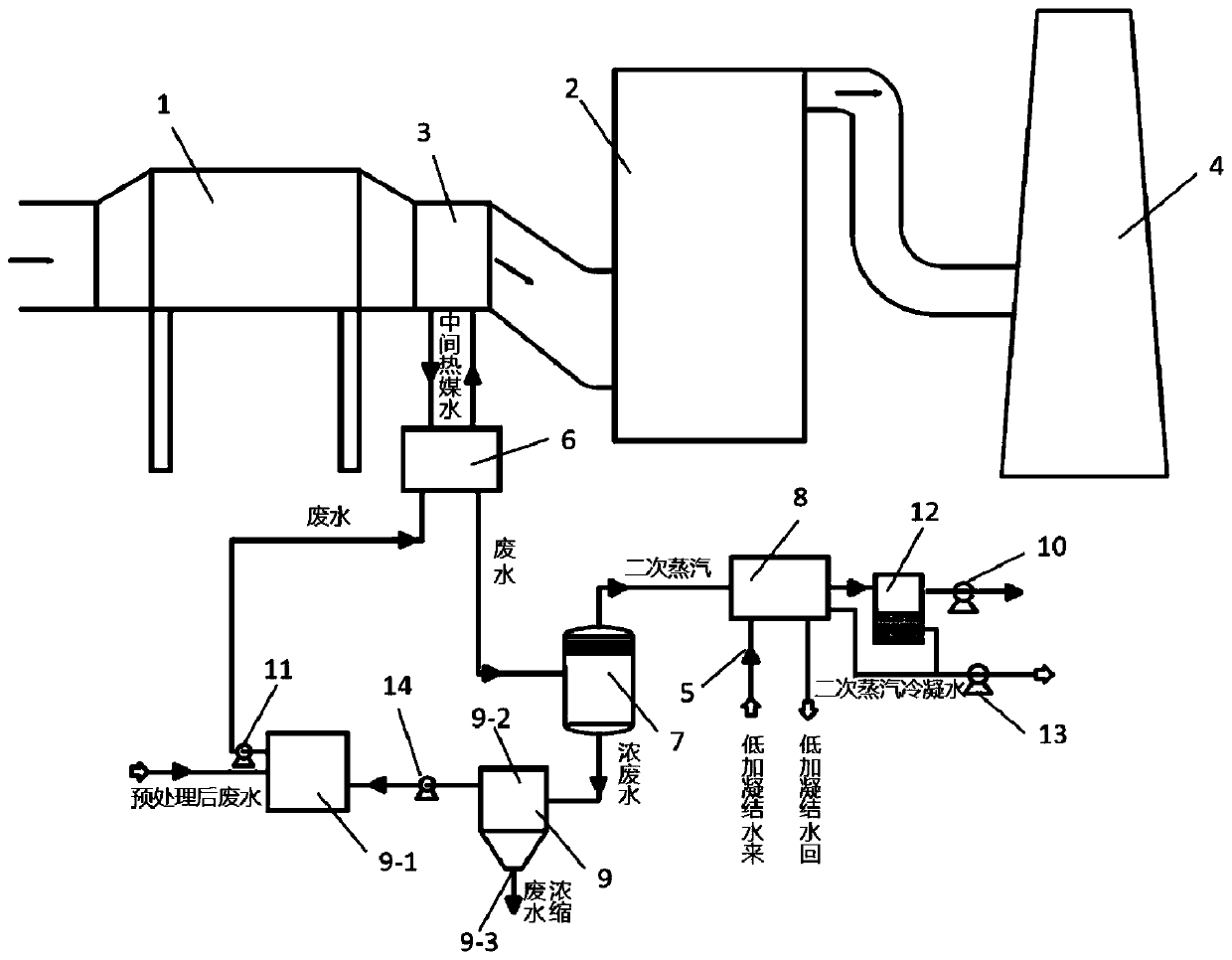
[0068] This embodiment provides a vacuum phase change wastewater concentration and flue gas waste heat recovery system, such as figure 1 As shown, it includes a dust removal unit 1 and a desulfurization unit 2 connected together, and also includes an economizer 3 and a wastewater concentration system. The economizer 3 is arranged between the dust removal unit 1 and the desulfurization unit 2, or is arranged along the direction of flue gas flow. Before dust removal unit 1; dust removal unit 1 is an electric dust collector, desulfurization unit 2 is a desulfurization tower, and economizer 3 is a low-temperature economizer. The setting of economizer 3 can improve the dust removal capacity of dust removal unit 1.

[0069] Such as figure 2 As shown, the waste water concentration system includes: a first heat exchanger 6, which communicates with the economizer 3, so that the waste water and the first heat exchange medium from the economizer 3 exchange heat in the first heat exchang...

Embodiment 2

[0094] Such as figure 1 As mentioned above, this embodiment provides a vacuum phase change wastewater concentration and flue gas waste heat recovery system, which includes a dust removal unit 1, a desulfurization unit 2, and a chimney 4 connected to each other, and also includes an economizer 3 and a wastewater concentration system, and the economizer 3 is set between the dust removal unit 1 and the desulfurization unit 2; the dust removal unit 1 is an electric precipitator, the desulfurization unit 2 is a desulfurization tower, and the economizer 3 is a low and low temperature economizer; the wastewater concentration system includes:

[0095] The first heat exchanger 6 communicates with the economizer 3, so that the waste water and the first heat exchange medium from the economizer 3 exchange heat in the first heat exchanger 6;

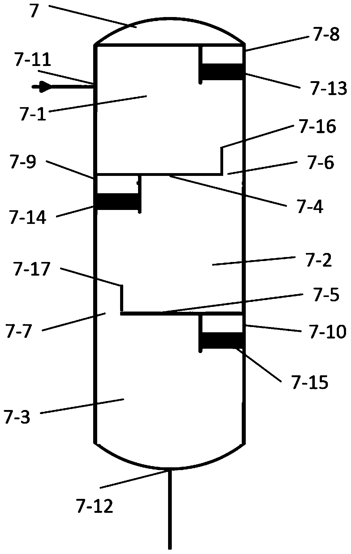
[0096] Flash tank 7, such as Figure 7 As shown, a first partition 7-4 and a second partition 7-5 are arranged inside, along the direction from the...


PUM

PropertyMeasurementUnit
heightaaaaaaaaaa

Abstract

According to a vacuum phase change wastewater concentration and flue gas waste heat recovery system provided by the invention, flue gas exchanges heat with a first heat exchange medium after passing through a coal economizer, and a flash tank realizes multistage flash evaporation by utilizing gradient vacuum, so that the concentration of desulfurization wastewater is facilitated; meanwhile, steamwith different temperatures can be formed through multi-stage flash evaporation, the steam and a second heat exchange medium are subjected to stepped heat exchange after entering the heat exchange assembly, and the heat exchange effect is improved; due to the economizer, the flue gas waste heat is used for increasing the wastewater temperature; after wastewater flash evaporation, recovered flue gas waste heat is brought out along with steam, the second heat exchange medium recovers heat contained in the steam, and finally the heat is returned to a low-pressure heater system, so that gradient utilization of heat energy is realized under the condition that the flue gas waste heat is hardly lost, the defect that high-quality heat energy is consumed by utilizing a conventional route is overcome, and the energy consumption of a unit is reduced. By means of the mode, waste water concentration is achieved, meanwhile, the problem of flue gas waste heat recovery of a coal-fired power plant or other industries is solved, and good social and economic influences are achieved.

Description

technical field [0001] The invention relates to the field of environmental protection technology, in particular to a vacuum phase change waste water concentration and flue gas waste heat recovery system, in particular to a system for waste heat recovery from flue gas in thermal power plants and waste water concentration. Background technique [0002] China's power energy is dominated by coal resources. With the increase of thermal power installed capacity, sulfur dioxide has become the main source of air pollution. Flue gas desulfurization (FGD) is the main process of industrial desulfurization. Among them, the wet limestone washing process has become the most common flue gas desulfurization technology because of its high desulfurization efficiency, good adaptability to coal types, mature process and reliable operation. However, desulfurization wastewater will be produced during the desulfurization process. The water quality and quantity characteristics of desulfurization wa...

Claims


Application Information

Patent Timeline
Patent Type & Authority Applications(China)
IPC IPC(8): C02F9/10C02F1/06C02F1/16F28D21/00C02F103/18
CPCC02F1/043C02F1/048C02F1/06C02F1/16C02F2001/007C02F2103/18F28D21/0001
Inventor 王争荣汪洋苏军划胡小夫夏怀鹏耿宣
Owner CHINA HUADIAN ENG
Why Eureka
Try Eureka