
Device and method for detecting disc repairing period of polishing die

A technology for detecting devices and polishing molds, which is applied in the direction of grinding devices, grinding/polishing equipment, and parts of grinding machine tools, etc., which can solve problems such as inconsistent wear of polishing molds, increased polishing costs, and waste of polishing mold repairs. Achieve the effects of improving processing efficiency and processing quality, ensuring grinding activity, and improving processing quality

Pending Publication Date: 2020-01-03
SHANGHAI INST OF OPTICS & FINE MECHANICS CHINESE ACAD OF SCI +1
View PDF0 Cites 3 Cited by
  • Summary
  • Abstract
  • Description
  • Claims
  • Application Information

AI Technical Summary

Problems solved by technology

[0004] The disadvantage of the traditional judgment method is that the method of recording the working time of the polishing mold is used. Due to factors such as the polishing speed, the speed of polishing liquid addition, and the temperature, the same working time will be caused, and the degree of wear of the polishing mold will be inconsistent.
Repairing the polishing mold too early will cause waste and destroy the polishing process; repairing the polishing mold too late will result in a decrease in polishing efficiency and an increase in polishing costs
The method of stopping the measurement will cause the pollution of the polishing mold and the reduction of polishing efficiency.

Method used


Image

  • Device and method for detecting disc repairing period of polishing die
  • Device and method for detecting disc repairing period of polishing die
  • Device and method for detecting disc repairing period of polishing die

Examples


Embodiment Construction

[0037] The present invention will be further described below in conjunction with embodiment, but should not limit the transformation range of the present invention with this.

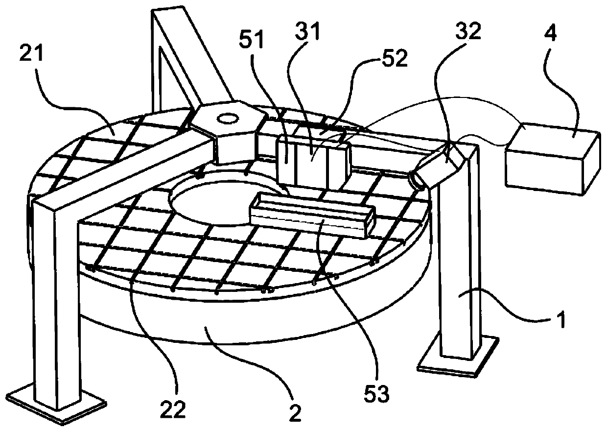
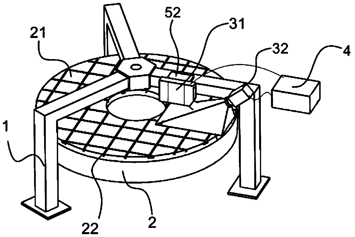
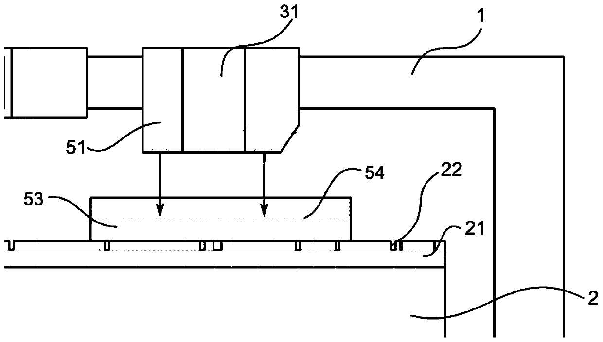
[0038] refer to figure 1 , figure 1 It is a detection device for a polishing mold disk repair cycle of the present invention, comprising: a polishing disk 2, the polishing disk 2 is a disc or an annular disk, a polishing mold 21 cast or pasted on the surface of the polishing disk 2, the polishing There is a groove 22 on the surface of the mold 21; the frame 1 located above the polishing disc 2 and fixedly connected to the ground; it is characterized in that it also includes an optical detection component for detecting the surface topography of the polishing mold 21 3. A processor 4, and a levelness measurement component 5 for measuring the horizontal installation error of the light source 31;

[0039]The levelness measurement assembly 5 includes: a laser displacement sensor 51, a connecting seat 52, a...


PUM


Abstract

The invention discloses a device and a method for detecting the disc repairing period of a polishing die. The device comprises an optical detecting component, a processor and a levelness measuring component. The optical detecting component uses structured light to detect the surface topography of the polishing die; and the processor calculates and processes to obtain the depth and width information of a groove in the surface of the polishing die through the received probe light comprising the surface topography information of the polishing die, so that the repairing period of the polishing dieis determined, and the maintaining time node of the polishing die is monitored. The device is simple in structure, precise in measurement and rapid in response, realizes in-situ detection of the discrepairing period of the polishing die, ensures the grinding activeness of the surface of the polishing die and improves the processing efficiency and the processing quality.

Description

technical field [0001] The invention relates to an auxiliary device for optical element ring polishing, in particular to the repairing cycle and working life of a polishing mold, and belongs to the technical field of optical element processing. Background technique [0002] The polishing process of optical components is usually to bond or cast a layer of polishing mold on the polishing disc driven by a motor, place one or more components to be processed on the polishing mold, and the components rotate at a specific angular speed. At the same time, the polishing liquid is added to the polishing mold, and the surface shape of the polishing mold is transferred and copied to the component through the mechanochemical action of the optical components and polishing powder particles on the polishing mold, so as to obtain a globally smooth planar component and complete the polishing of the component. [0003] The commonly used polishing mold material for polishing is generally asphal...

Claims


Application Information

Patent Timeline
IPC IPC(8): B24B37/005B24B37/34B24B49/12
CPCB24B37/005B24B37/34B24B49/12
Inventor 陈军邵建达张慧方吴伦哲杨明红吴福林秦豪杰
Owner SHANGHAI INST OF OPTICS & FINE MECHANICS CHINESE ACAD OF SCI
Learn More