
Clamping and turning device for assistance in glass edge grinding

A steering device and glass edging technology, which is applied to the grinding drive device, machine tools suitable for grinding workpiece edges, grinding machines, etc. Improve clamping and grinding efficiency, convenient clamping and fixing operation, and convenient assembly and installation.

Inactive Publication Date: 2020-01-03
蚌埠市万德精密机械有限公司
View PDF0 Cites 4 Cited by
  • Summary
  • Abstract
  • Description
  • Claims
  • Application Information

AI Technical Summary

Problems solved by technology

[0002] In the process of glass production and processing, it is necessary to clamp and fix the glass with a suction cup when edging the glass. When the suction cup clamps and fixes the glass, the vacuum degree of negative pressure adsorption is unstable when the glass is edged. At the same time, the glass is prone to adsorption and loosening, resulting in a decrease in the quality of glass edging; at the same time, the glass needs to be changed and polished during the edging process. The existing operation is that the operator manually flips the glass, and then performs adsorption and clamping. It is time-consuming and labor-intensive, and the operation is complicated, and it is not easy to operate and use. There is a risk of cutting when the glass is turned over and the labor cost is increased. Therefore, we design a clamping and turning device for auxiliary glass edging

Method used


Image

  • Clamping and turning device for assistance in glass edge grinding
  • Clamping and turning device for assistance in glass edge grinding
  • Clamping and turning device for assistance in glass edge grinding

Examples


Embodiment Construction

[0018] The technical solutions in the embodiments of the present invention will be clearly and completely described below in conjunction with the accompanying drawings in the embodiments of the present invention. Obviously, the described embodiments are only some of the embodiments of the present invention, not all of them; based on The embodiments of the present invention and all other embodiments obtained by persons of ordinary skill in the art without creative efforts all belong to the protection scope of the present invention.

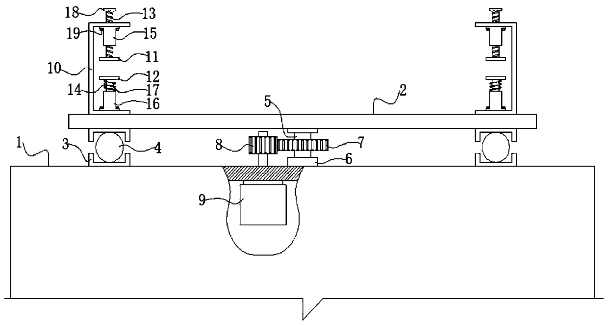
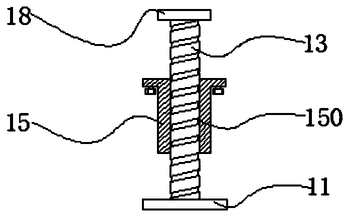
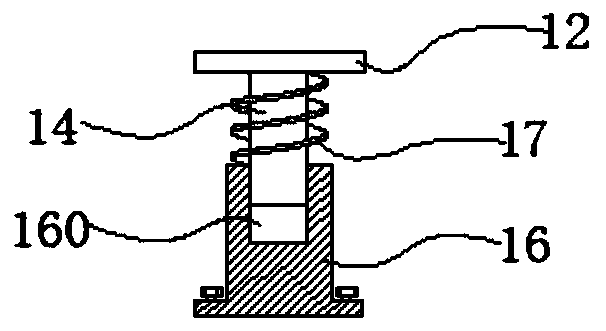
[0019] Such as Figure 1-3 As shown, the specific embodiment of the present invention: a clamping and steering device for auxiliary glass edging, including a base box 1 and a rotating platen 2 arranged directly above the base box 1, the upper surface of the base box 1 Corresponding to the lower surface of the rotating platen 2, an annular slideway groove 3 is installed, and a ball 4 for easy rotation is arranged in the annular slideway groove 3, an...


PUM


Abstract

The invention discloses a clamping and turning device for assistance in glass edge grinding. The device comprises a base box and a rotating table plate arranged right above the base box, the middle position of the lower surface of the rotating table plate is fixedly connected with the top end of a rotating shaft, a bearing seat is rotatably assembled and installed at the bottom end of the rotatingshaft, the bearing seat is fixedly installed on the upper surface of the base box, a driven gear is fixedly installed on the rotating shaft in a sleeving mode, the driven gear is in meshing transmission connection with a driving gear, the driving gear is fixedly installed on the output shaft end of a rotating motor in a sleeving mode, U-shaped plates are symmetrically and fixedly connected to theleft side and the right side of the upper surface of the rotating table plate, an upper threaded sleeve and a lower column seat are fixedly installed on the upper inner plate wall and the lower innerplate wall of the U-shaped plate respectively, a screw rod is installed in the upper threaded sleeve in a threaded fit mode, an upper clamping plate is fixedly connected to the bottom end of the screw rod, a buffer supporting column is inserted into the top end of the lower column seat, and a lower clamping plate is fixedly connected to the top end of the buffer supporting column. By adopting thetechnical scheme, the operation is time-saving and labor-saving, and the clamping and grinding efficiency of glass can be improved.

Description

technical field [0001] The invention relates to the technical field of glass processing, in particular to a clamping and steering device for auxiliary glass edging. Background technique [0002] In the process of glass production and processing, it is necessary to clamp and fix the glass with a suction cup when edging the glass. When the suction cup clamps and fixes the glass, the vacuum degree of negative pressure adsorption is unstable when the glass is edged. At the same time, the glass is prone to adsorption and loosening, resulting in a decrease in the quality of glass edging; at the same time, the glass needs to be changed and polished during the edging process. It is time-consuming and labor-intensive, and the operation is complicated, and it is not easy to operate and use. There is a risk of cutting when turning the glass and increasing labor costs. Therefore, we design a clamping and steering device for glass edging assistance. Contents of the invention [0003] ...

Claims


Application Information

Patent Timeline
Patent Type & Authority Applications(China)
IPC IPC(8): B24B9/08B24B41/06B24B41/00B24B47/12B24B41/02
CPCB24B9/08B24B41/007B24B41/02B24B41/068B24B47/12
Inventor 张鹏陈佩伟黄猛
Owner 蚌埠市万德精密机械有限公司
Learn More