Transparent conductive film and image display device
A technology of transparent conductivity and transparent conductive layer, applied in the direction of conductive layer on insulating carrier, equipment for manufacturing conductive/semiconductive layer, electrical digital data processing, etc., can solve the problem of light transmittance reduction and achieve good Translucency, the effect of suppressing recognition
- Summary
- Abstract
- Description
- Claims
- Application Information
AI Technical Summary
Problems solved by technology
Method used
Image

Examples
Embodiment approach
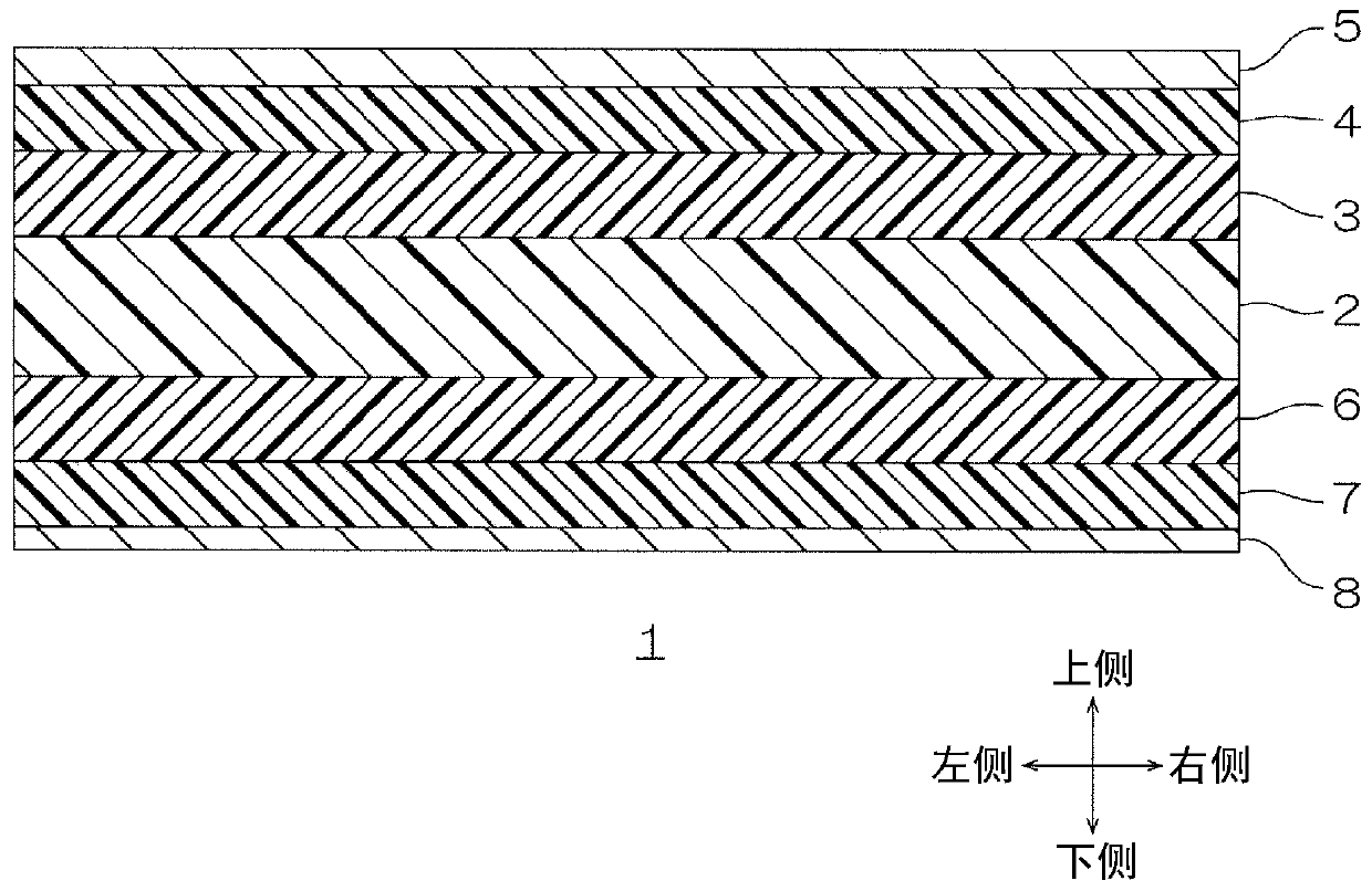
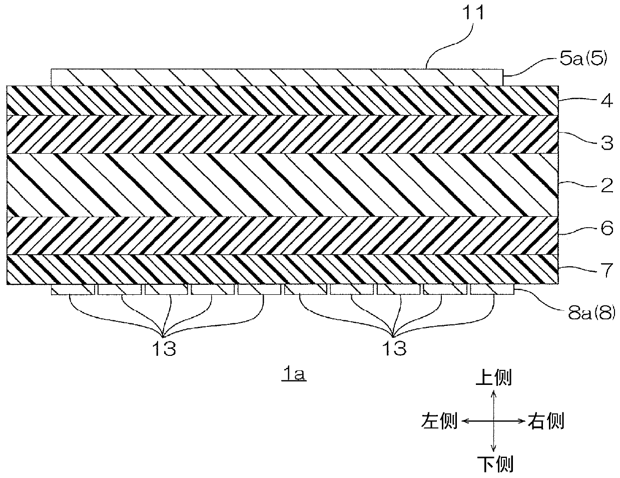
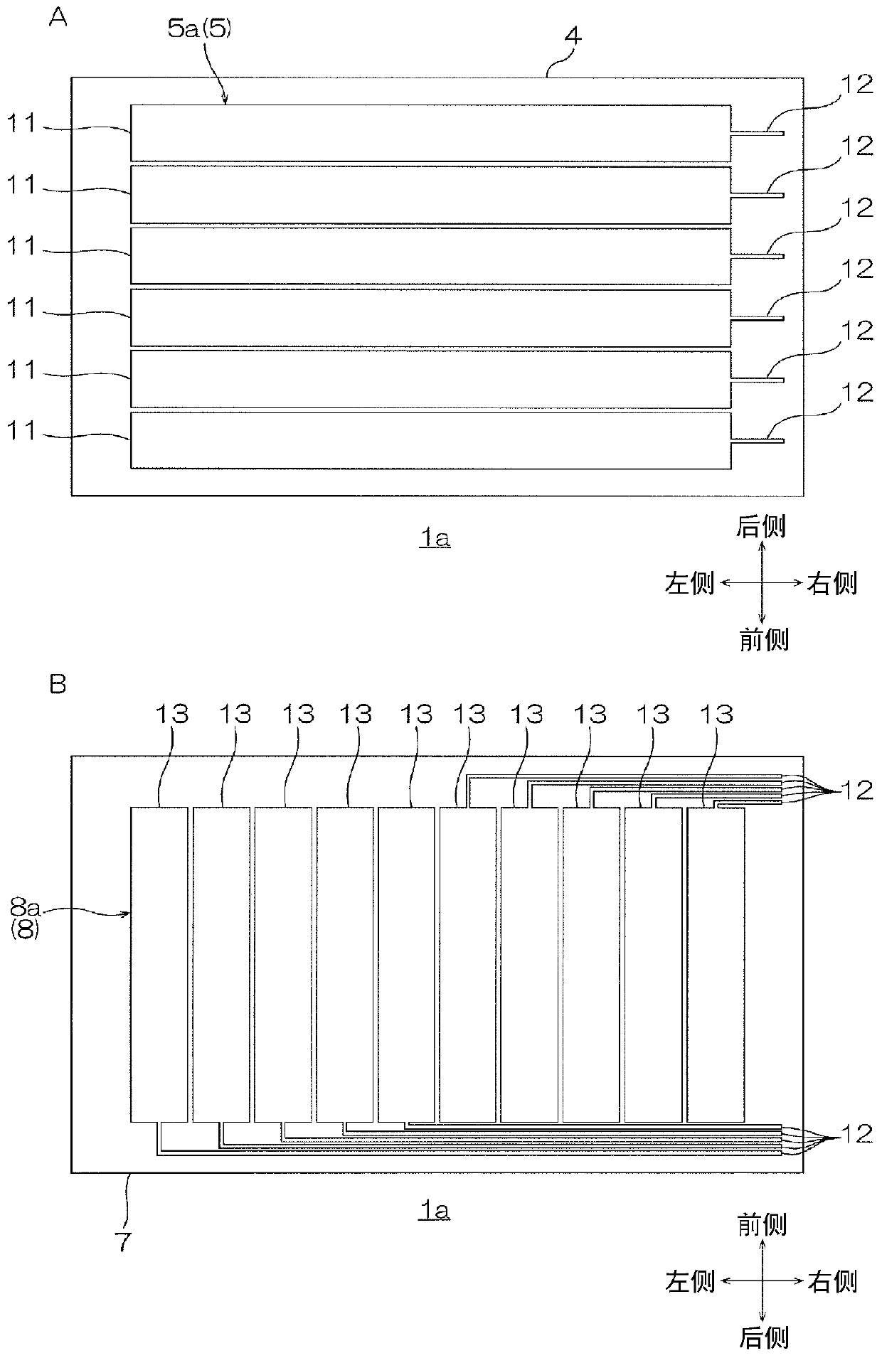
[0033] One embodiment of the transparent conductive film of the present invention will be described below with reference to the drawings. figure 1 Among them, the upper and lower directions on the paper are the up and down directions (thickness direction, first direction), the upper side on the paper is the upper side (one side in the thickness direction, the first direction side), and the lower side on the paper is the lower side (the other side in the thickness direction). side, the other side in the first direction). In addition, the left-right direction of the paper is the left-right direction (the second direction, the direction perpendicular to the first direction), the left side of the paper is the left side (the second direction side), and the right side of the paper is the right side (the second direction). 2 direction to the other side). In addition, the thickness direction of the paper is the depth direction (the third direction, the direction perpendicular to the...
Embodiment 1
[0177] A hard coat composition (acrylic ultraviolet curable resin, manufactured by DIC Corporation, manufactured by DIC Corporation, "UNIDIC RS29-120") was dried by heating at 80°C for 1 minute. Thereafter, ultraviolet rays were irradiated using a high-pressure mercury lamp to form first and second hard coat layers (each having a thickness of 1.0 μm and each having a refractive index of 1.53). Thereby, the laminated body of a 1st hard-coat layer, a transparent base material, and a 2nd hard-coat layer was obtained.
[0178] Next, a diluent of the optical adjustment composition having a refractive index of 1.70 was applied to the surface of the first hard coat layer of the laminate with a gravure coater, and heat-dried at 60° C. for 1 minute. Thereafter, ultraviolet rays were irradiated using a high-pressure mercury lamp to form a first optical adjustment layer (refractive index: 1.70, thickness: 80 nm). Moreover, except having used the optical adjustment composition with a re...
Embodiment 2~9 and comparative example 1~5
[0184] In addition to changing the thickness and refractive index of the optical adjustment layer, and the thickness and surface resistance of the transparent conductive layer to the thickness and refractive index of the optical adjustment layer and the thickness and surface resistance of the transparent conductive layer described in Table 1, , A transparent conductive film was produced by the same method as in Example 1.
PUM
| Property | Measurement | Unit |
|---|---|---|
| Surface resistance | aaaaa | aaaaa |
| Surface resistance | aaaaa | aaaaa |
| Thickness | aaaaa | aaaaa |
Abstract
Description
Claims
Application Information
 - R&D
- Intellectual Property
- Life Sciences
- Materials
- Tech Scout
- Unparalleled Data Quality
- Higher Quality Content
- 60% Fewer Hallucinations
Browse by: Latest US Patents, China's latest patents, Technical Efficacy Thesaurus, Application Domain, Technology Topic, Popular Technical Reports.
© 2025 PatSnap. All rights reserved.Legal|Privacy policy|Modern Slavery Act Transparency Statement|Sitemap|About US| Contact US: help@patsnap.com