Cutting device

A technology for cutting devices and cutting tools, which is applied in the direction of abrasive surface adjustment devices, grinding machine parts, grinding/polishing equipment, etc., can solve problems such as wrong recognition, unrecognizable two-dimensional codes, and two-dimensional code defects, etc., to achieve The effect of suppressing errors

Pending Publication Date: 2019-07-19
DISCO CORP
View PDF8 Cites 0 Cited by
  • Summary
  • Abstract
  • Description
  • Claims
  • Application Information

AI Technical Summary

Problems solved by technology

[0005] However, in the cutting device shown in Patent Document 1, when the surface to be cut is cut with a two-dimensional code formed on the surface to be cut of the trimming plate, the two-dimensional code may be chipped, and the two-dimensional code may not be recognized afterwards. Dimensional codes lead to incorrect identification of the type of trim

Method used


Image

  • Cutting device
  • Cutting device
  • Cutting device

Examples


Embodiment approach 1

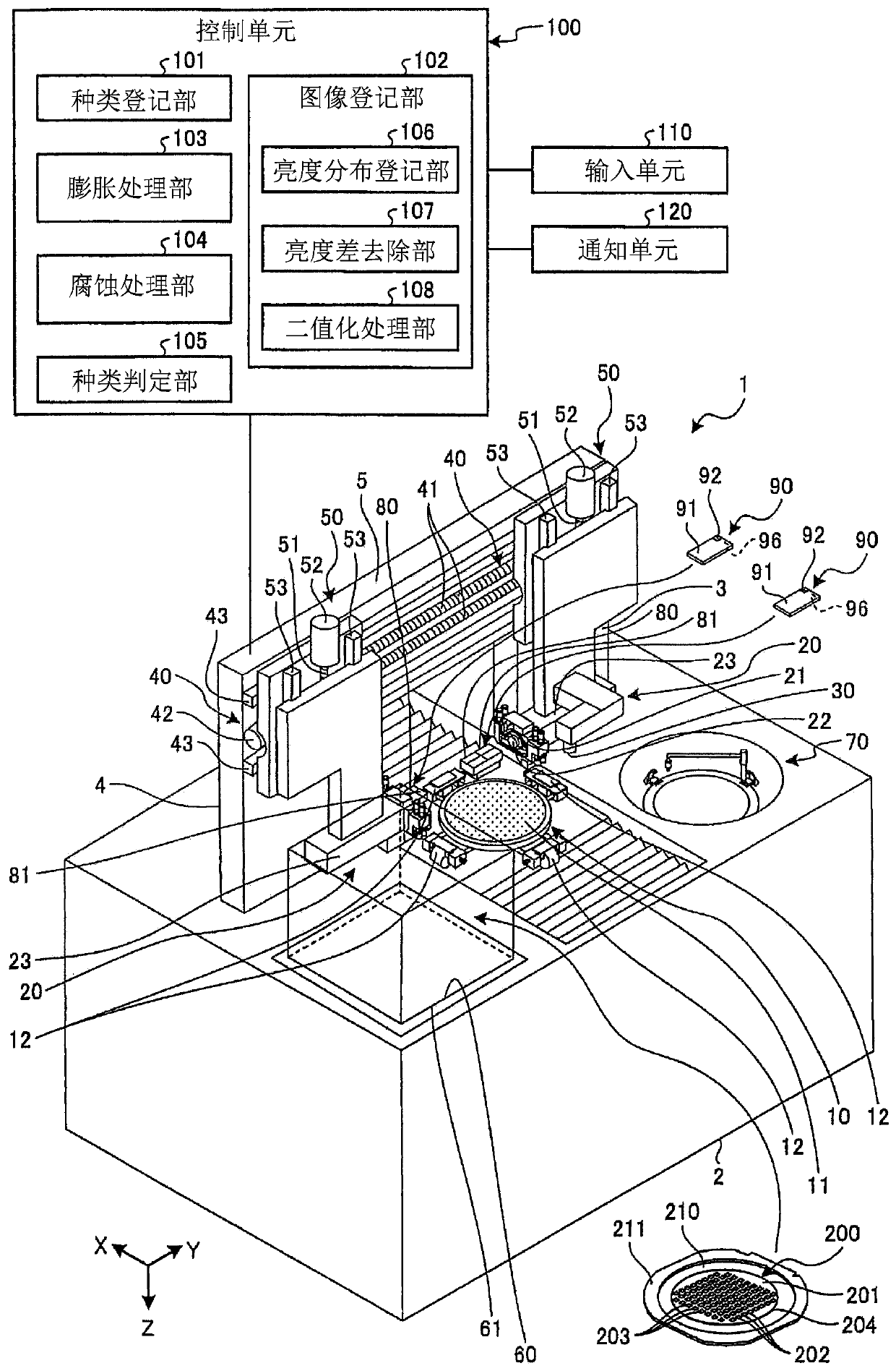
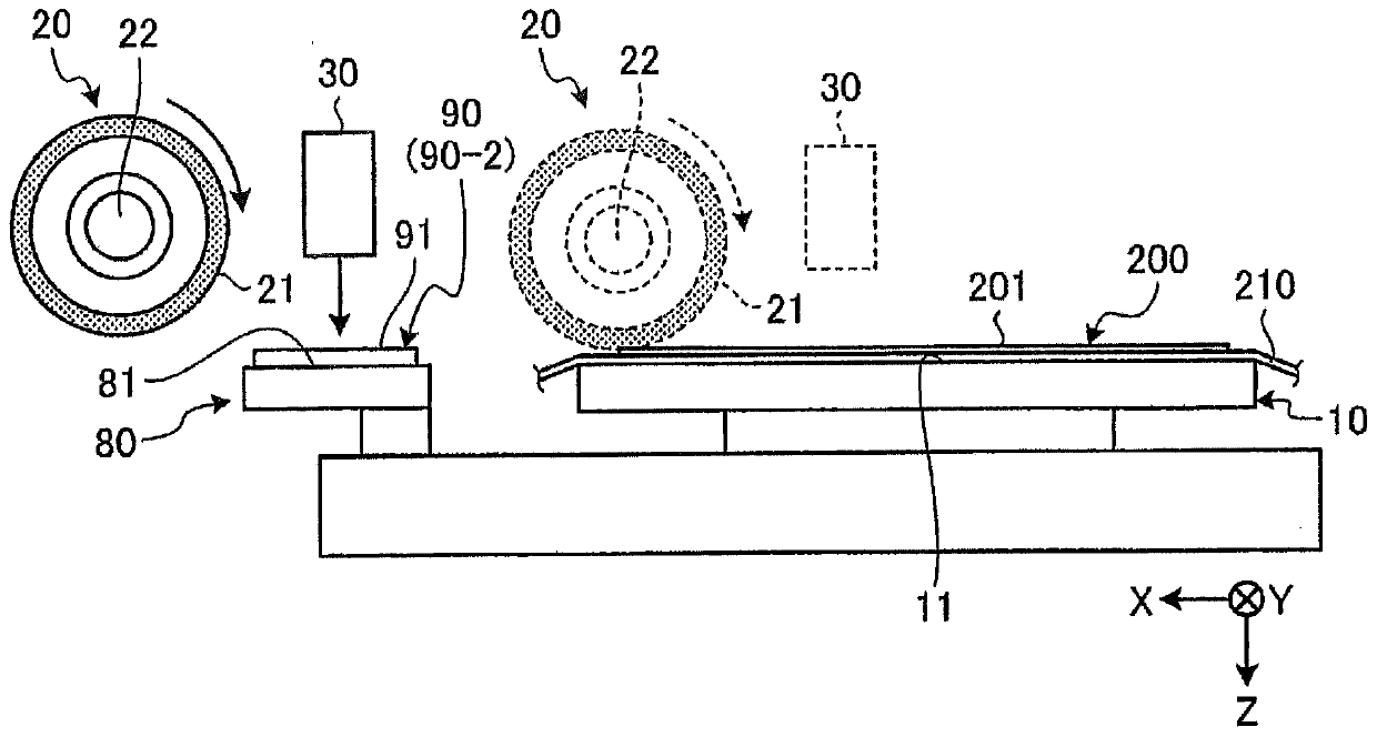
[0029] The cutting device according to Embodiment 1 of the present invention will be described with reference to the drawings. figure 1 It is a perspective view which shows the structural example of the cutting apparatus of Embodiment 1. FIG. figure 2 is shown figure 1 A diagram of the main part of the cutting unit of the cutting apparatus shown. image 3 is shown figure 1 Side view of the main part of the cutting device shown. Figure 4 is shown figure 1 A plan view of an example of a dressing plate of the shown cutting device. Figure 5 will Figure 4 The top view shown in the enlarged view of the V part.

[0030] The cutting apparatus 1 of Embodiment 1 is an apparatus which cuts (processes) the workpiece 200 which is a plate-like object. In Embodiment 1, the workpiece 200 is a disk-shaped semiconductor wafer or an optical device wafer having silicon, sapphire, gallium, or the like as a base material. The workpiece 200 has a device 203 formed on the front surface 20...


PUM


Abstract

Provided is a cutting device capable of suppressing misrecognition of a kind of a dressing board in which a cut surface is cut. The cutting device (1) is provided with a dressing board (90) provided with a two-dimensional code (9) composed of a plurality of cells; and a control unit (100) for determining the kind of the dressing board (90) based on an image photographed by a camera (30). The control unit (100) comprises a kind registration part (101) which registers the kind information of the dressing board (90); an image registration part (102) which registers the photographed image in whichthe dressing board (90) is photographed and binary-ized; a dilation processing part (103) which performs dilation processing on the photographed image; an erosion processing part (104) for performingerosion processing on the photographed image subjected to dilation processing; and a kind determination part (105) for reading out the kind information of the dressing board (90) from the two-dimensional code (9) restored by the erosion processing.

Description

technical field [0001] The present invention relates to cutting devices. Background technique [0002] Immediately after the cutting tool is attached to the spindle, abrasive grains are embedded in the bonding material, or the rotation center of the spindle is offset from the rotation center of the attached cutting tool. Therefore, the following dressing is performed: The bonding is formed by cutting the dressing plate. Material consumption, aligning the center of rotation, allowing abrasive particles to protrude from the bonded material. [0003] There are many types of dressing plates depending on the application and the type of cutting tool for cutting. When trimming is performed with the wrong combination of the trimming plate and the cutting tool, the trimming plate cannot be effective. Therefore, it is important to reliably attach a desired trimming plate to the cutting device. In order to ensure that an incorrect trimming plate is not attached to the cutting device,...

Claims


Application Information

Patent Timeline
Patent Type & Authority Applications(China)
IPC IPC(8): B24B53/12B24B27/06
CPCB24B53/12B24B27/0683
Inventor 荒生一树津野贵彦
Owner DISCO CORP
Why Eureka
Try Eureka