
3*3 Butler matrix

A matrix and coupler technology, which is applied in the field of microwave passive devices, can solve the problems of inconvenient layout of the whole antenna, increase of matrix board area, high cost, etc., achieve high application prospects and use value, facilitate batch welding, and good stability Effect

Pending Publication Date: 2019-12-31
TONGYU COMM INC
View PDF0 Cites 1 Cited by
  • Summary
  • Abstract
  • Description
  • Claims
  • Application Information

AI Technical Summary

Problems solved by technology

[0002] There are mainly two implementation methods for existing similar matrix boards. One of the implementation methods is microstrip line, which adopts the scheme of cascading branch line couplers. The main disadvantage of this scheme is that a single branch line coupler can only achieve 20% If you want to achieve a bandwidth of more than 50%, you need to cascade multiple branch line couplers, which will undoubtedly greatly increase the area of ​​the matrix board and bring great inconvenience to the overall layout of the antenna; another The implementation method is stripline, which adopts the solution of cascading stripline couplers. This solution solves the problem of too large area of ​​the above-mentioned microstrip line solution, and can reach more than 50% of the bandwidth, but is limited by the implementation of stripline form, which has the disadvantages of high cost and difficulty in cascading welding with commonly used feeder networks, which will cause the whole machine to easily generate intermodulation hazards and be difficult to maintain

Method used


Image

  • 3*3 Butler matrix

Examples


Embodiment Construction

[0014] In order to make the purpose, technical solutions and advantages of the embodiments of the present invention clearer, the technical solutions in the embodiments of the present invention will be clearly and completely described below in conjunction with the accompanying drawings in the present invention. Obviously, the described embodiments are the Some embodiments of the invention are not all embodiments. Based on the embodiments of the present invention, all other embodiments obtained by those of ordinary skill in the art without creative efforts fall within the protection scope of the present invention.

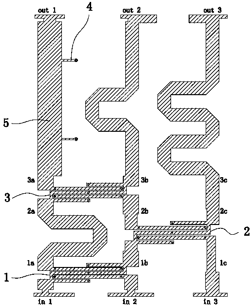
[0015] A 3×3 Butler matrix, comprising a first Lange coupler 1, a second Lange coupler 2, a third Lange coupler 3 and several short-circuit stubs 4; wherein each Lange coupler has two input terminals and Two output terminals, respectively the first input terminal, the second input terminal, the first output terminal and the second output terminal;

[0016] The 3×3But...


PUM


Abstract

The invention provides a 3*3 Butler matrix. The matrix comprises a first Lange coupler, a second Lange coupler, a third Lange coupler and several short circuit branches. Through cascade connection ofthe multiple Lange couplers and a microstrip line, a stable 120 degree phase difference in a three-beam antenna matrix can be realized, an implementation mode of the microstrip line is low in cost, and is good in stability, batch welding is convenient and a radio frequency cable is easily connected to form a complete machine. Besides, a Lange bridge is innovatively adopted to replace a branch linecoupler scheme, characteristics of a small size, an ultra-wide band and high isolation are possessed, and the matrix adapts to a development trend of miniaturization and wideband of a base station antenna, and has a very high application prospect and a use value.

Description

technical field [0001] The invention relates to the technical field of microwave passive devices, in particular to a 3*3 Butler matrix. Background technique [0002] There are mainly two implementation methods for existing similar matrix boards. One of the implementation methods is microstrip line, which adopts the scheme of cascading branch line couplers. The main disadvantage of this scheme is that a single branch line coupler can only achieve 20% If you want to achieve a bandwidth of more than 50%, you need to cascade multiple branch line couplers, which will undoubtedly greatly increase the area of ​​the matrix board and bring great inconvenience to the overall layout of the antenna; another The implementation method is stripline, which adopts the solution of cascading stripline couplers. This solution solves the problem of too large area of ​​the above-mentioned microstrip line solution, and can reach more than 50% of the bandwidth, but is limited by the implementation ...

Claims


Application Information

Patent Timeline
IPC IPC(8): H01P5/08H01P5/18H01P5/00
CPCH01P5/08H01P5/00H01P5/184
Inventor 吕士禄何建华李泓霖赵伟
Owner TONGYU COMM INC
Learn More