Optical imaging lens and imaging equipment
An optical imaging lens and lens technology, used in optics, optical components, instruments, etc., can solve the problem of less cameras, and achieve the effect of correcting field curvature and astigmatism, increasing the amount of light passing through, and achieving good imaging effects.
- Summary
- Abstract
- Description
- Claims
- Application Information
AI Technical Summary
Problems solved by technology
Method used
Image

Examples
no. 1 example
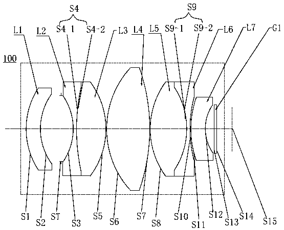
[0074] see figure 1 , the optical imaging lens 100 provided in this embodiment includes in sequence from the object side to the image side: a first lens L1, a stop ST, a second lens L2, a third lens L3, a fourth lens L4, a fifth lens L5, a Six lenses L6, a seventh lens L7 and a filter G1.
[0075] The first lens L1 has a negative refractive power, the object side S1 of the first lens is a convex surface, the image side S2 of the first lens is a concave surface, and the first lens L1 is a glass aspherical lens;
[0076] The second lens L2 has negative refractive power, and the object side S3 of the second lens and the image side S4-1 of the second lens are both concave surfaces;
[0077] The third lens L3 has positive refractive power, the object side S4-2 of the third lens, and the image side S5 of the third lens are both convex surfaces, the second lens L2 and the third lens L3 form a cemented body and both are glass spherical lenses, also That is, the image side S4-1 of th...
no. 2 example
[0091] For the structural schematic diagram of the optical imaging lens 200 provided in this embodiment, please refer to Figure 5 , the optical imaging lens 200 in this embodiment is roughly the same as the optical imaging lens 100 in the first embodiment, except that the first lens L1 has positive refractive power, and the curvature radius and material selection of each lens are different.
[0092] The relevant parameters of each lens in the optical imaging lens 200 provided in this embodiment are shown in Table 3.
[0093] table 3
[0094]
[0095] In addition, the parameters of each aspheric lens in this embodiment are shown in Table 4.
[0096] Table 4
[0097]
[0098] In this embodiment, its distortion, curvature of field and axial aberration curves are as follows Figure 6 , Figure 7 and Figure 8 shown by Figure 6 , Figure 7 and Figure 8 It can be seen that distortion, field curvature and axial aberration can all be well corrected in this embodiment....
no. 3 example
[0100] For the structural diagram of the optical imaging lens 300 provided by the third embodiment of the present invention, please refer to Figure 9 , the structure of the optical imaging lens 300 in this embodiment is roughly the same as that of the optical imaging lens 100 in the first embodiment, except that the first lens L1 is a glass spherical lens with positive refractive power, the second lens L2 and The third lens L3 is an independent lens (the two do not form a cemented body), and the curvature radius and material selection of each lens are different.
[0101] The relevant parameters of each lens in the optical imaging lens 300 provided in this embodiment are shown in Table 5.
[0102] table 5
[0103]
[0104] The parameters of each aspheric lens in this embodiment are shown in Table 6.
[0105] table 6
[0106]
[0107] In this embodiment, its distortion, curvature of field and axial aberration curves are shown as Figure 10 , Figure 11 and Figure 12 ...
PUM
 Abstract
Description
Claims
Application Information
 - R&D
- Intellectual Property
- Life Sciences
- Materials
- Tech Scout
- Unparalleled Data Quality
- Higher Quality Content
- 60% Fewer Hallucinations
Browse by: Latest US Patents, China's latest patents, Technical Efficacy Thesaurus, Application Domain, Technology Topic, Popular Technical Reports.
© 2025 PatSnap. All rights reserved.Legal|Privacy policy|Modern Slavery Act Transparency Statement|Sitemap|About US| Contact US: help@patsnap.com