
Terahertz SAR multi-frequency vibration error compensation method

A vibration error and compensation method technology, applied in the direction of reflection/re-radiation of radio waves, utilization of re-radiation, measurement devices, etc., can solve the problems of large amount of calculation, limited scope of application and poor real-time performance

Inactive Publication Date: 2019-12-31
SHANGHAI RADIO EQUIP RES INST
View PDF6 Cites 4 Cited by
  • Summary
  • Abstract
  • Description
  • Claims
  • Application Information

AI Technical Summary

Problems solved by technology

The improved method that has been proposed so far is the discrete sinusoidal frequency modulation transform (DSFMT) to estimate the sinusoidal frequency modulation signal parameters introduced by high-frequency vibration in the radar echo, but this method needs to solve the multi-dimensional space optimization problem in the estimation of multi-frequency vibration components, and the amount of calculation is large. Big, poor real-time performance
Another feasible method is Chirplet decomposition and its improved adaptive Chirplet decomposition. Compared with DSFMT, this method can accurately estimate multiple chirp signal components, but it also has the problem of a large amount of calculation, and this method has a large impact on the signal High noise ratio requirements, limited scope of application
Some scholars proposed not to estimate the high-frequency vibration parameters of multiple frequencies, but to directly apply the self-focusing algorithm for motion compensation of multi-frequency vibrations, but from the simulation results, the compensation effect is limited

Method used


Image

  • Terahertz SAR multi-frequency vibration error compensation method
  • Terahertz SAR multi-frequency vibration error compensation method
  • Terahertz SAR multi-frequency vibration error compensation method

Examples


Embodiment Construction

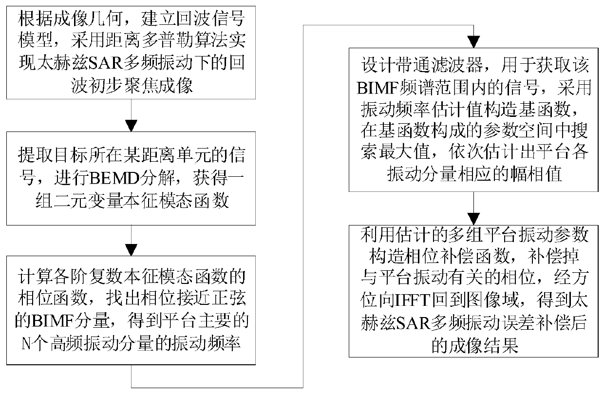
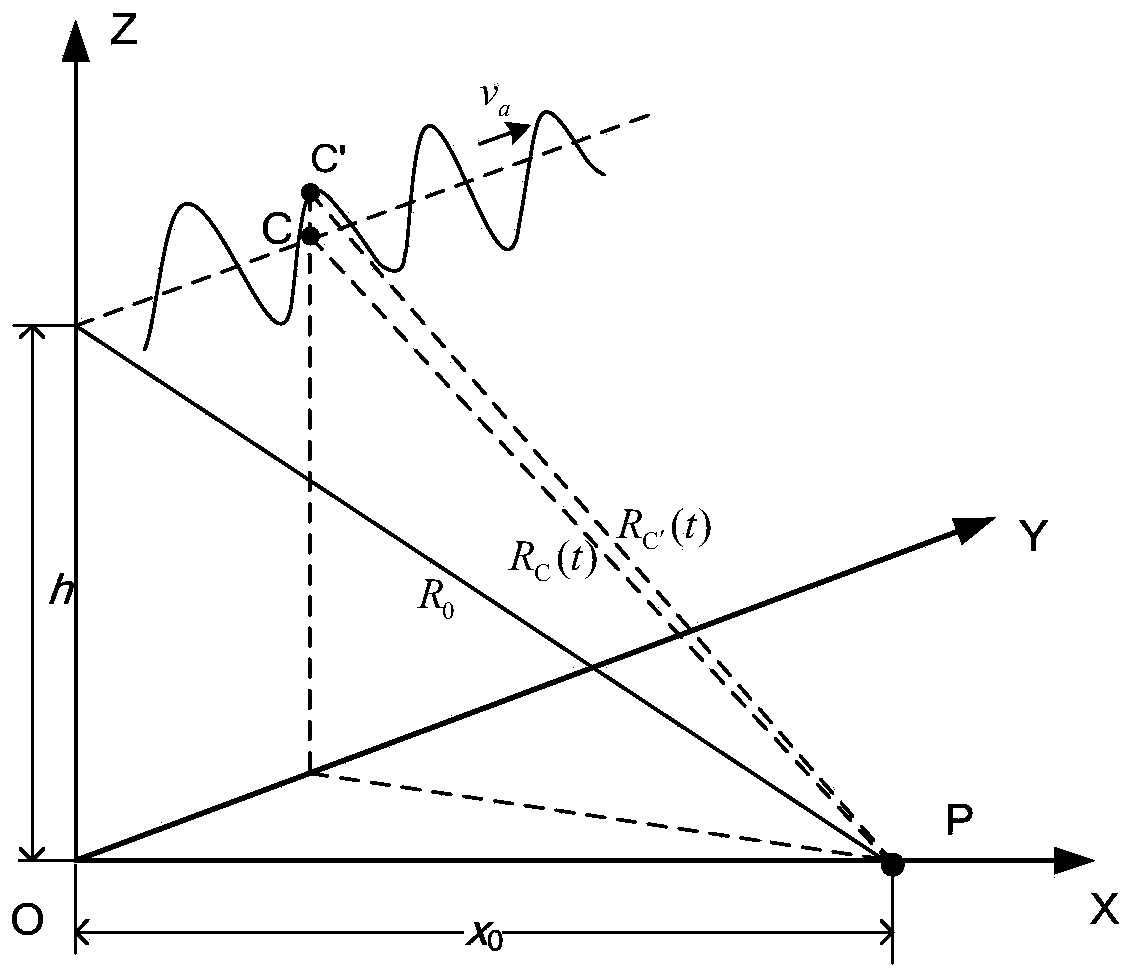
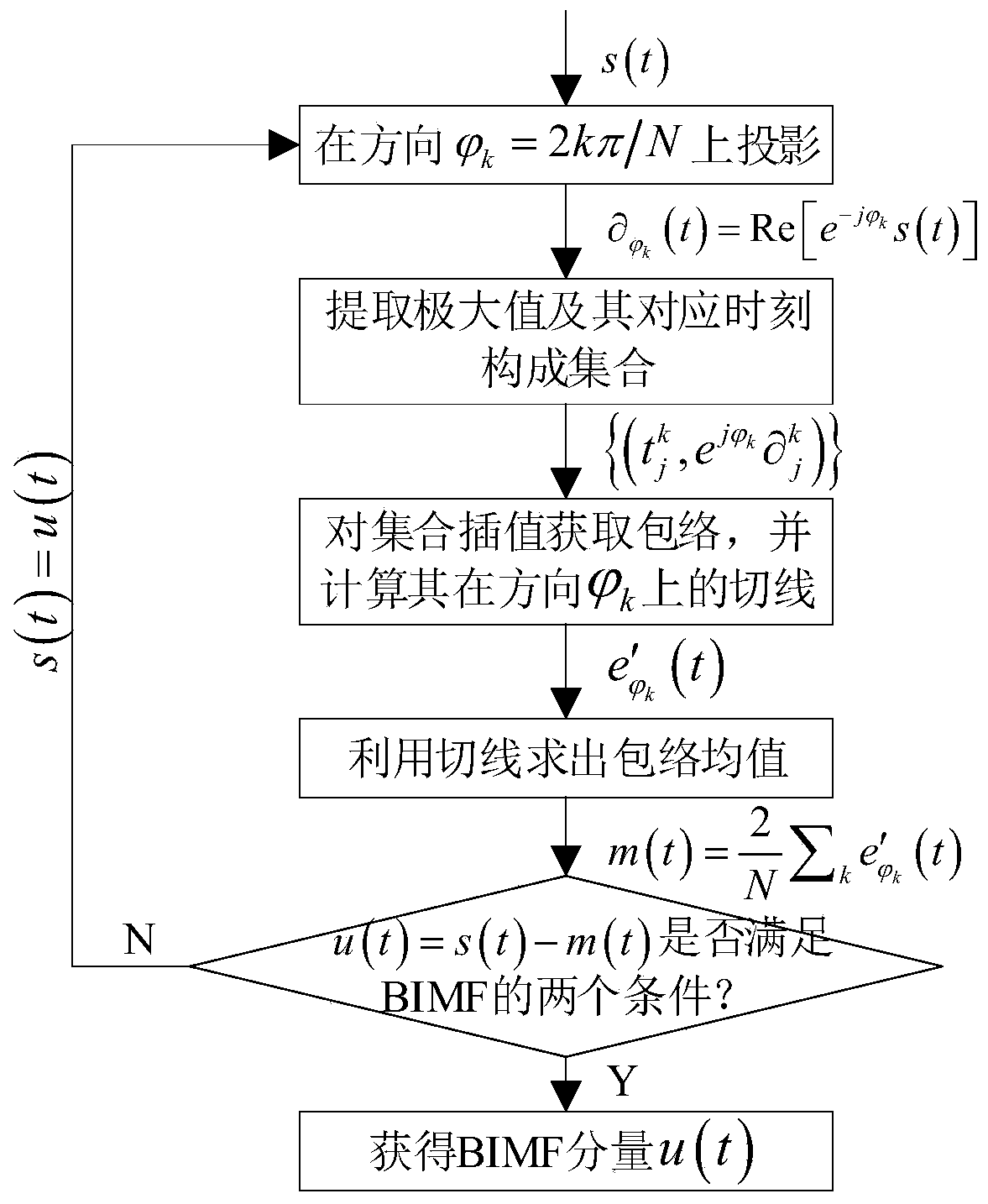
[0052] The invention provides a terahertz SAR multi-frequency vibration error compensation method. According to the multi-frequency vibration geometric model of the terahertz SAR platform, this method obtains the influence of the terahertz SAR platform vibration on the instantaneous slant distance of SAR imaging, establishes the echo signal model under the multi-frequency vibration of the terahertz SAR, and analyzes the pulse pressure of the echo by distance Finally, the high-frequency vibration of the terahertz SAR platform will affect the distance travel of the signal and introduce the secondary phase, and use the terahertz SAR high-frequency vibration imaging method based on Doppler keystone transformation to complete the focus of the echo; then, for the imaging The relationship between the phase of the result and the platform vibration parameters, the binary variable empirical mode decomposition (BEMD) is introduced to separate the platform vibration components and the vibr...


PUM


Abstract

The invention relates to a terahertz synthetic aperture radar (SAR) multi-frequency vibration error compensation method. Platform vibration, especially high-frequency vibration, may introduce additional phases related to the vibration frequency into a radar azimuth signal, which may cause a terahertz SAR image to be out of focus and present a phenomenon of paired echo. The method of the inventionincludes the following steps of: establishing an echo signal model under the terahertz SAR multi-frequency vibration according to a multi-frequency vibration geometric model of a terahertz SAR platform; completing paired echo focusing by adopting a terahertz SAR high-frequency vibration imaging method, introducing BEMD decomposition to perform platform vibration component separation and vibrationfrequency estimation, sequentially selecting BIMF components in high-frequency sinusoidal form to carry out time domain reconstruction, adopting a parameter space method to find a peak value, determining the amplitude and initial phase of the vibration component, and constructing a compensation function to complete the high-frequency vibration error compensation of the platform until no significant high-frequency vibration components are detected. The scheme of the invention realizes accurate compensation of terahertz SAR multi-frequency vibration errors, and effectively improves the imaging quality of the actual terahertz SAR platform.

Description

technical field [0001] The invention relates to the technical field of radar signal processing, in particular to a terahertz SAR multi-frequency vibration error compensation method. Background technique [0002] Terahertz waves generally refer to electromagnetic radiation with a frequency between 0.1 THz and 10 THz, and a wavelength of 3 mm to 30 μm. In terms of frequency, terahertz waves are between millimeter waves and infrared light; in terms of energy, terahertz waves are between electrons and photons. Due to the special properties of terahertz waves, using them in synthetic aperture radar imaging can break many bottlenecks in traditional optical radar and millimeter-wave radar imaging. Compared with optical radar, Terahertz Synthetic Aperture Radar (THz-SAR) has high transmittance, can penetrate dielectric materials to detect hidden objects, and can be used in the field of security inspection and quality inspection; compared with microwave and millimeter wave radar , ...

Claims


Application Information

Patent Timeline
IPC IPC(8): G01S13/90G01S7/40
CPCG01S7/40G01S13/9029G01S13/9019
Inventor 夏慧婷胡秋野王洁阚学超
Owner SHANGHAI RADIO EQUIP RES INST
Learn More