


Quick Research
Generate reliable direction feasibility study reports for your R&D in just a few steps.

Technical Q&A
Discover and master advanced knowledge NOW. Basics, ideas, possibilities, all at once.

Find Solutions
As an expert in R&D theories, this can generate solutions to your technical problems instantly.

Evaluate Feasibility
Analyze your overall solution with one click, know your potential R&D risks in advance.

Monitor Landscape
Get weekly tech updates, stay abreast of the latest tech innovations and key insights.
Dewatering construction method for deep foundation pit
A construction method and technology of deep foundation pits, which are applied in basic structure engineering, components of pumping devices for elastic fluids, variable capacity pump components, etc., can solve problems such as damage to pumps and inconvenient turnover and transportation, and achieve improvement Long service life, easy to use outdoors, avoid collision
- Summary
- Abstract
- Description
- Claims
- Application Information
AI Technical Summary
Problems solved by technology
Method used
Image

Examples
Embodiment
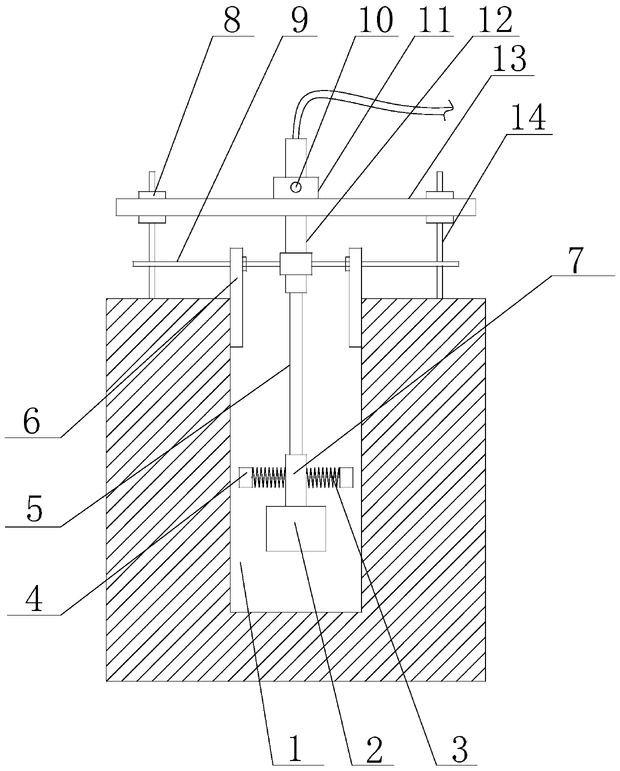
[0042] Such as Figure 1 to Figure 5 Shown, a kind of deep foundation pit dewatering construction method of the present invention comprises the following steps:
[0043] 1) Connect the second steel pipe 12 of the suction pipe with the second positioning ring 16, then connect the cross bar 9 with the second positioning ring 16, connect the embedded rod 14 with the cross bar 9 through threads, and connect the embedded rod 14 fixed around the deep well 1;
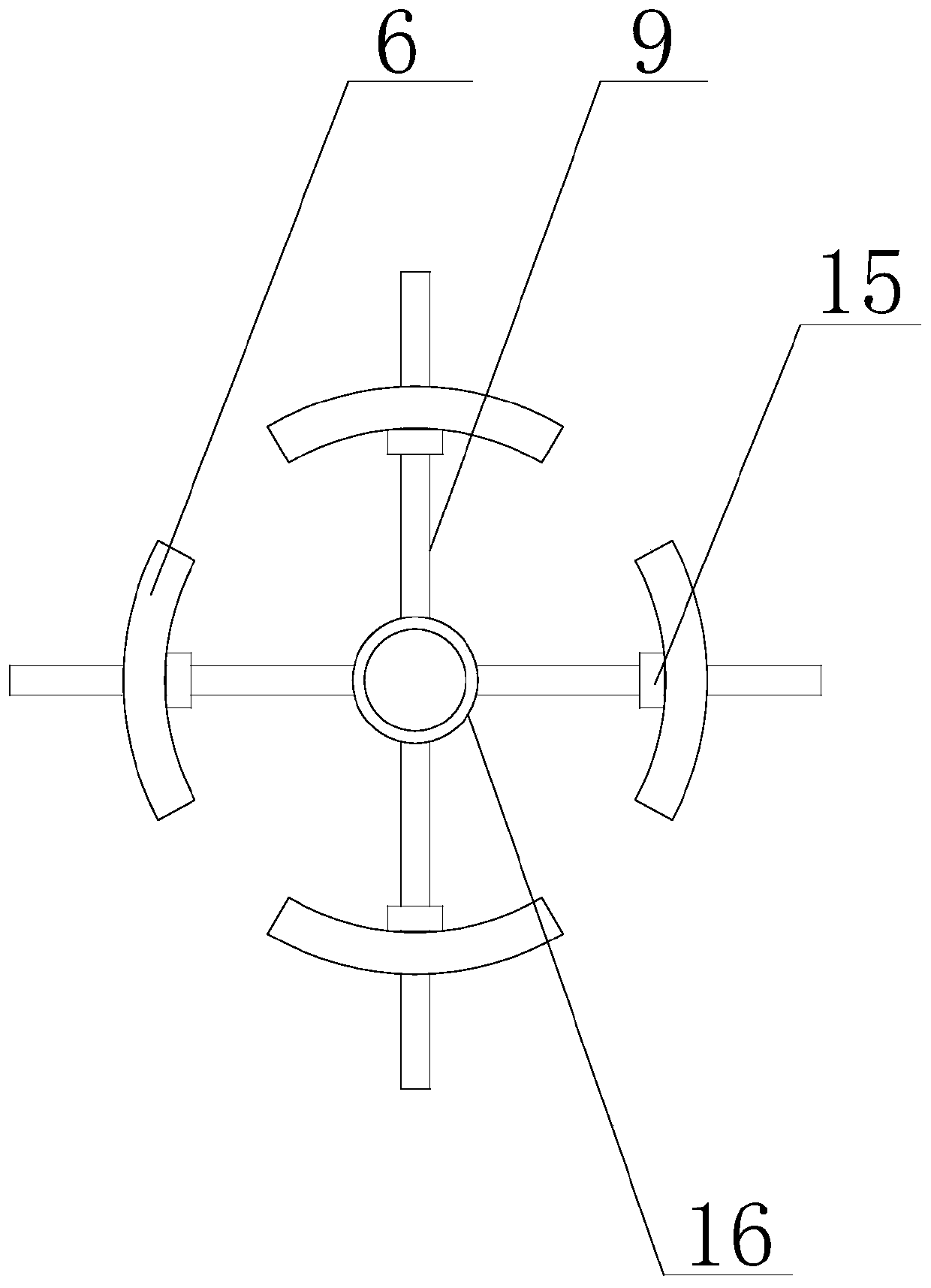
[0044] 2) Adjust the position of the support plate 6 according to the diameter of the wellhead 1 of the deep well 1, so that the support plate 6 is tightly pressed against the inner wall of the wellhead;
[0045] 3) Put the water pump 2 into the deep well 1, when the water pump 2 is put into the deep well 1, the anti-collision block 4 protects the water pump 2;
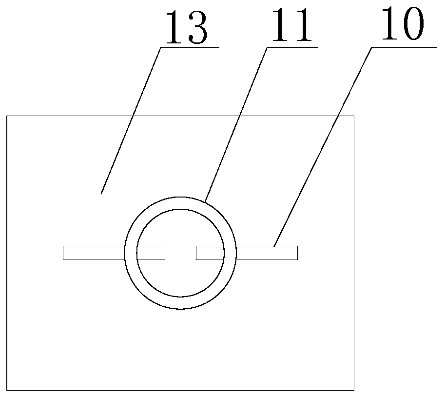
[0046] 4) Connect the horizontal plate 13 with the embedded rod 14 through the fixing ring 8, and connect the second steel pipe 12 of the water suction pipe with the ...
Embodiment 2
[0053] On the basis of Embodiment 1, the cross section of the support plate 6 is an arc structure.
Embodiment 3
[0055] On the basis of Embodiment 1, the pumping pipe includes a first steel pipe 7, a flexible pipe 5 and a second steel pipe 12, and the two ends of the flexible pipe 5 are respectively connected with the first steel pipe 7 and the second steel pipe 12, and the buffer 3 is located on the outer wall of the first steel pipe 7, and the second steel pipe 12 is located in the second positioning ring 16. The outer wall of the second positioning ring 16 is also provided with two second fixing rods 18, the second fixing rods 18 are located on both sides of the axis of the second positioning ring 16, and the second fixing rods 18 are located below the cross bar 9 , the crossbar 9 is horizontally connected to the second positioning ring 16 through threads, and the crossbar 9 can fix the second steel pipe 12 in the second positioning ring 16 .
PUM
 Abstract
Description
Claims
Application Information
 - R&D Engineer
- R&D Manager
- IP Professional
- Industry Leading Data Capabilities
- Powerful AI technology
- Patent DNA Extraction
Browse by: Latest US Patents, China's latest patents, Technical Efficacy Thesaurus, Application Domain, Technology Topic, Popular Technical Reports.
© 2024 PatSnap. All rights reserved.Legal|Privacy policy|Modern Slavery Act Transparency Statement|Sitemap|About US| Contact US: help@patsnap.com