Transport and dumping device

A technology of dumping device and conveying plate, applied in the directions of transportation and packaging, conveyor objects, etc., can solve the problems of large fluid flow resistance and leakage, high maintenance and use cost, limited application scope, etc., achieving long service life, convenient maintenance, Use a wide range of effects

Pending Publication Date: 2019-12-31
SHANGHAI JIAN QIAO UNIV
View PDF2 Cites 1 Cited by
  • Summary
  • Abstract
  • Description
  • Claims
  • Application Information

AI Technical Summary

Problems solved by technology

The hydraulic device has large fluid flow resistance and leakage, serious pollution, the working environment is limited by the liquid medium, and the maintenance and use cost is high
And mechanical device, comprises adopting gear transmission, as disclosed in Chinese patent CN208747182U bagged raw material dumping device and spring for feed processing, or draw-in device, such as a kind of kimchi altar lifting dumping device disclosed in Chinese patent CN 208307946U etc., complex in structure , the scope of application is limited

Method used


Image

  • Transport and dumping device
  • Transport and dumping device
  • Transport and dumping device

Examples


Embodiment 1

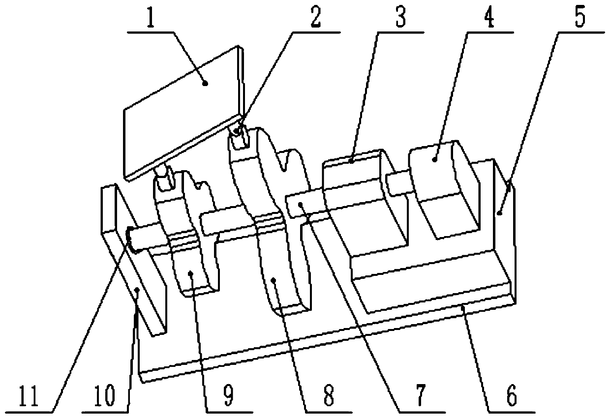
[0026] A transport dumping device, the structure of which is as figure 1 As shown, the device is mainly composed of three mechanisms: the frame, the power supply part and the rotating and lifting part. Wherein, the frame includes a base plate 6, a support plate 10 arranged on the base plate 6 and a motor seat 5, the support plate 10 is arranged on one side of the base plate 6, and the motor seat 5 is positioned at the other side of the base plate 6 relative to the support plate 10, for example , in this embodiment, the support plate 10 is arranged on the left side of the base plate 6 , and the motor seat 5 is located on the upper surface of the right side of the base plate 6 .

[0027] The power supply part includes a motor 4 and a gearbox 3 arranged on a motor seat 5 arranged on the base plate 6. The motor and the gearbox adopt backrest wheels or other connections, utilize the motor 4 to provide power, and utilize the gearbox 3 to change the output of power, thereby Change t...

Embodiment 2

[0045] A transport dumping device, the structure of which is roughly the same as that of Embodiment 1, the difference is that the middle part of this embodiment contains a motor seat, and the gearbox and the motor are directly installed on the bottom plate.

Embodiment 3

[0047] A transport dumping device, the structure of which is roughly the same as that of Embodiment 1, the difference is that three special-shaped wheels are provided in this embodiment, and the three special-shaped wheels are respectively connected to three rotating shafts, and each rotating shaft is arranged concentrically. Keep the RPM the same.


PUM


Abstract

The invention relates to a transport and dumping device. The device comprises a rack, a power supply part and a rotation lifting part. The rack is composed of a baseplate (6) and a supporting plate (10) arranged on the baseplate (6); the power supply part comprises a motor (4) and a gearbox (3) which are arranged on the baseplate (6); the rotation lifting part comprises a rotation shaft (7), two or more special-shaped wheels, a conveying plate (1), two or more push rods (2) and a bearing (11), one end of the rotation shaft (7) is connected with an output end of the gearbox (3), the other end of the rotation shaft (7) is installed on the supporting plate (10) through the bearing (11), the special-shaped wheels penetrate through the rotation shaft (7), the number of the push rods (2) is identical to that of the special-shaped wheels, one end of each push rod (2) is connected with the conveying plate (1), and the other end of each push rod (2) abuts against the outer side of the corresponding special-shaped wheel so that the push rods can slide along the surfaces of the special-shaped wheels. Compared with the prior art, the transport and dumping device achieves the lifting and dumping functions of a mechanism and is simple in structure, free of pollution and wide in application range, and the application environment is not limited by the temperature, geographic positions, workingconditions and the like.

Description

technical field [0001] The invention relates to a dumping device, in particular to a transport dumping device. Background technique [0002] Currently, most dumping devices are either hydraulic or mechanical. The hydraulic device has large fluid flow resistance and leakage, serious pollution, the working environment is limited by the liquid medium, and the maintenance and use cost is high. And mechanical device, comprises adopting gear transmission, as disclosed in Chinese patent CN208747182U bagged raw material dumping device and spring for feed processing, or draw-in device, such as a kind of kimchi altar lifting dumping device disclosed in Chinese patent CN 208307946U etc., complex in structure , the scope of application is limited. Contents of the invention [0003] The object of the present invention is to provide a transport dumping device in order to overcome the above-mentioned defects in the prior art. [0004] The purpose of the present invention can be achiev...

Claims


Application Information

Patent Timeline
Patent Type & Authority Applications(China)
IPC IPC(8): B65G47/74
CPCB65G47/74
Inventor 岳春晓陈苏婷
Owner SHANGHAI JIAN QIAO UNIV
Why Eureka
Try Eureka