
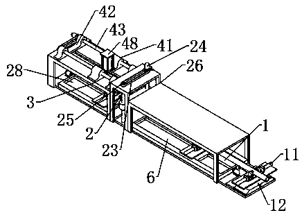
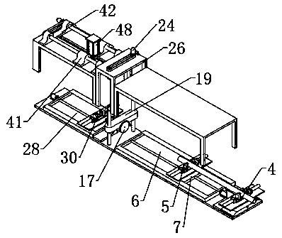
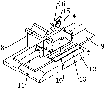
Circular tube cutting and surface drilling integrated equipment

A round pipe and equipment technology, which is applied in the field of round pipe cutting and surface drilling integrated equipment, can solve the problems of not being easy to fix, increasing labor costs, wasting time, etc.

Active Publication Date: 2019-12-31
重庆优实管业有限公司
View PDF7 Cites 3 Cited by
  • Summary
  • Abstract
  • Description
  • Claims
  • Application Information

AI Technical Summary

Problems solved by technology

[0002] Round pipe is a common pipe material. When using round pipe as a machine component, it is necessary to drill holes in the steel pipe to facilitate the connection and positioning of the steel pipe. At present, the preparation of these holes is controlled manually, that is, at both ends of each long pipe The positioning line is drawn on the upper and lower curved surfaces of the head and punched with a sample, and then the pipe is fixed on the machine tool for drilling hole by hole. Since the steel or plastic pipe itself is round and not easy to fix, it is difficult to fix it during processing. It is easy to miss the hole or make a long round hole, not only the accuracy is difficult to grasp, but also the drilling position is not easy to control
[0003] At present, after the round pipe is cut, the round pipe is put into the drilling device for drilling. After each cut, it will be sent to the drilling machine for drilling in the middle of the transfer, which will waste time and increase labor costs. Therefore, It is necessary to design a cutting and drilling integrated equipment

Method used


Image

  • Circular tube cutting and surface drilling integrated equipment
  • Circular tube cutting and surface drilling integrated equipment
  • Circular tube cutting and surface drilling integrated equipment

Examples


Embodiment Construction

[0023] The technical solutions of the present invention will be further described below in conjunction with the accompanying drawings and through specific implementation methods.

[0024] Wherein, the accompanying drawings are only for illustrative purposes, showing only schematic diagrams, rather than physical drawings, and should not be construed as limitations on this patent; in order to better illustrate the embodiments of the present invention, some parts of the accompanying drawings will be omitted, Enlargement or reduction does not represent the size of the actual product; for those skilled in the art, it is understandable that certain known structures and their descriptions in the drawings may be omitted.

[0025] In the drawings of the embodiments of the present invention, the same or similar symbols correspond to the same or similar components; , "inner", "outer" and other indicated orientations or positional relationships are based on the orientations or positional ...


PUM


Abstract

The invention relates to the machining field, in particular to circular tube cutting and surface drilling integrated equipment. The circular tube cutting and surface drilling integrated equipment comprises a feeding assembly, a cutting assembly and a drilling assembly, wherein the feeding assembly is arranged at one side of the cutting assembly; the drilling assembly is arranged at one side, awayfrom the feeding assembly, of the cutting assembly; the feeding assembly, the cutting assembly and the drilling assembly are linearly arranged in sequence; the feeding assembly comprises a fixed clampand a first movable clamp; the fixed clamp is arranged at one end of the cutting assembly; and the first movable clamp is arranged between the fixed clamp and the cutting assembly. The circular tubecutting and surface drilling integrated equipment solves the problem that circular tube cutting and drilling cannot be performed simultaneously, improves working efficiency and saves time.

Description

technical field [0001] The invention relates to the field of mechanical processing, in particular to an integrated equipment for cutting circular pipes and drilling holes on the surface. Background technique [0002] Round pipe is a common pipe material. When using round pipe as a machine component, it is necessary to drill holes in the steel pipe to facilitate the connection and positioning of the steel pipe. At present, the preparation of these holes is controlled manually, that is, at both ends of each long pipe The positioning line is drawn on the upper and lower curved surfaces of the head and punched with a sample, and then the pipe is fixed on the machine tool for drilling hole by hole. Since the steel or plastic pipe itself is round and not easy to fix, it is difficult to fix it during processing. When drilling, it is easy to miss or punch the hole into a long round hole, not only the accuracy is difficult to grasp, but also the position of the drilling is not easy t...

Claims


Application Information

Patent Timeline
Patent Type & Authority Applications(China)
IPC IPC(8): B23P23/02B23Q7/00B23Q3/08
CPCB23P23/02B23Q3/064B23Q3/08B23Q7/00B23Q2703/04
Inventor 姚国成
Owner 重庆优实管业有限公司
Learn More