
Method for improving preparation yield of FBAR filter and FBAR filter

A filter and yield technology, applied in electrical components, impedance networks, etc., can solve problems such as the adverse effect of filter structure, and achieve the effect of improving Q value and electromechanical coupling coefficient, not easy to collapse, and reducing insertion loss

Pending Publication Date: 2019-12-27
广州市艾佛光通科技有限公司
View PDF0 Cites 2 Cited by
  • Summary
  • Abstract
  • Description
  • Claims
  • Application Information

AI Technical Summary

Problems solved by technology

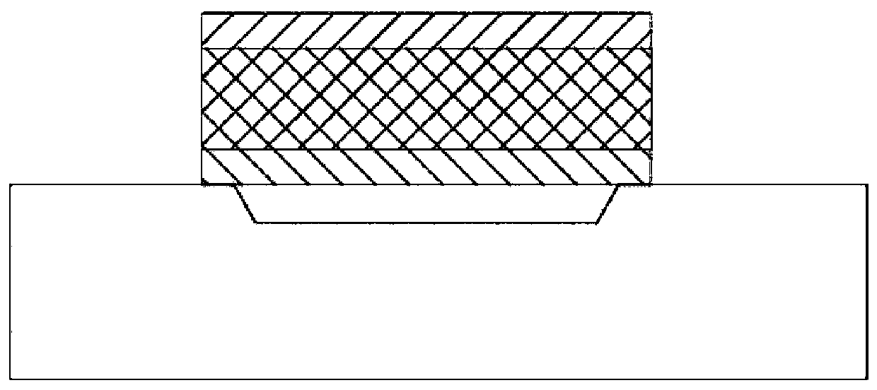
[0004] In order to overcome the deficiencies of the prior art, the present invention proposes a method for improving the yield rate of FBAR filters and FBAR filters. In the preparation process, no sacrificial layer is used, and the integrity of the piezoelectric film is retained, thereby overcoming the problem of During the process of removing the sacrificial layer, the filter structure is adversely affected, and the structural design of openings on the bonded substrate has a stable structure and is not easy to collapse, which can improve the quality of the piezoelectric film and reduce the filter The insertion loss of the filter improves the Q value and the electromechanical coupling coefficient, and will become a solution for RF filters in high-frequency and high-power applications in the future

Method used


Image

  • Method for improving preparation yield of FBAR filter and FBAR filter
  • Method for improving preparation yield of FBAR filter and FBAR filter
  • Method for improving preparation yield of FBAR filter and FBAR filter

Examples


Embodiment Construction

[0034] Below, the present invention will be further described in conjunction with the accompanying drawings and specific implementation methods. It should be noted that, under the premise of not conflicting, the various embodiments described below or the technical features can be combined arbitrarily to form new embodiments. .

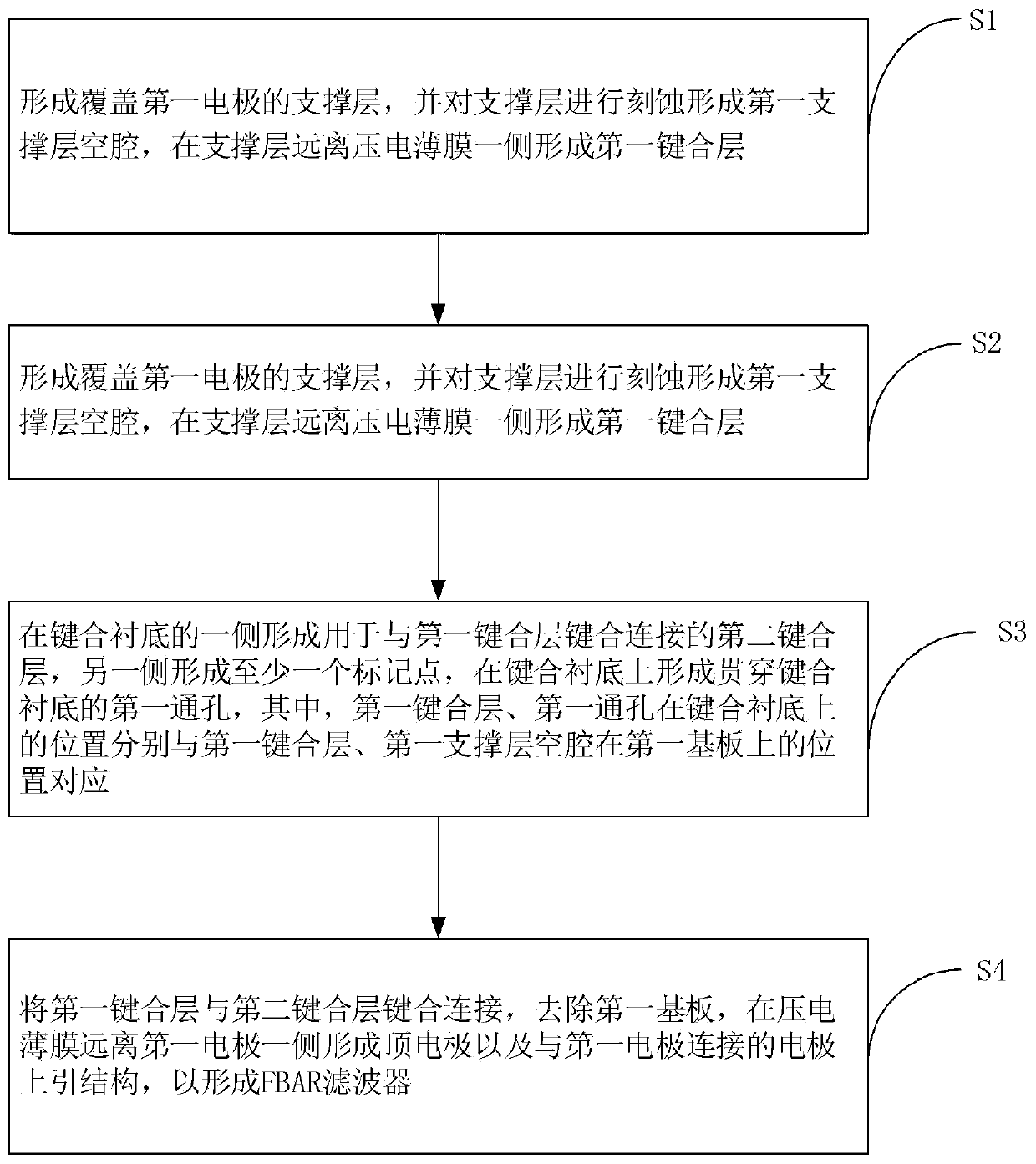
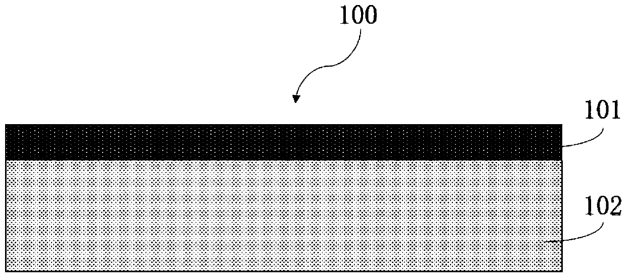
[0035] see Figure 2-18 ,in, figure 2 A flow chart of an embodiment of the method for improving the FBAR filter preparation yield of the present invention; image 3It is a schematic diagram of an embodiment of forming a piezoelectric thin film on the first substrate in the method for improving the FBAR filter preparation yield of the present invention; Figure 4 It is a schematic diagram of an embodiment of forming the first electrode on the piezoelectric film in the method for improving the FBAR filter preparation yield of the present invention; Figure 5 It is a schematic diagram of an embodiment of forming the first insulating layer in the metho...


PUM


Abstract

The invention provides a method for improving the preparation yield of an FBAR filter and the FBAR filter. The method comprises the following steps: generating a piezoelectric film on a first substrate, and forming at least one first electrode; forming a support layer, etching the support layer to form a first support layer cavity, and forming a first bonding layer on one side of the support layer; forming at least one mark point on the second bonding layer on one side of the bonding substrate and forming a first through hole penetrating through the bonding substrate on the bonding substrate;bonding and connecting the first bonding layer and the second bonding layer, removing the first substrate, and forming a top electrode and an electrode up-leading structure connected with the first electrode on one side, far away from the first electrode, of the piezoelectric film, so as to form the FBAR filter. In the preparation process, a sacrificial layer is not required to be used, the integrity of the piezoelectric film is kept, and the structural design that the holes are formed in the bonding substrate is stable in structure and not easy to collapse, so that the quality of the piezoelectric film can be well improved.

Description

technical field [0001] The invention relates to the technical field of electronic communication devices, in particular to a method for improving the production yield of an FBAR filter and the FBAR filter. Background technique [0002] The multi-functional development of wireless communication terminals has put forward high technical requirements for radio frequency devices such as miniaturization, high frequency, high performance, low power consumption, and low cost. The traditional surface acoustic wave filter (SAW) has a large insertion loss in the high frequency band above 2.4GHz, and the dielectric filter has good performance but is too large. Film Bulk Acoustic Resonator (FBAR) technology is a new radio frequency device technology that has emerged in recent years with the improvement of processing technology and the rapid development of modern wireless communication technology, especially personal wireless communication technology. It has a very high quality factor Q v...

Claims


Application Information

Patent Timeline
Patent Type & Authority Applications(China)
IPC IPC(8): H03H9/54H03H9/17H03H9/02H03H3/02
CPCH03H3/02H03H9/02007H03H9/171H03H9/54H03H2003/023
Inventor 李国强
Owner 广州市艾佛光通科技有限公司
Learn More