A hot-swap-based automatic disassembly split chassis system and working method

A technology of automatic disassembly and working methods, which is applied in the direction of digital processing power distribution, instruments, calculations, etc., and can solve the problems of inconvenient change and use of functional modules

Active Publication Date: 2020-11-13
HARBIN UNIV +1
View PDF6 Cites 0 Cited by
  • Summary
  • Abstract
  • Description
  • Claims
  • Application Information

AI Technical Summary

Problems solved by technology

For different purposes and usage scenarios, the chassis in the prior art cannot easily disassemble and replace functional modules, so it is not convenient for users to change the functional modules used according to needs

Method used


Image

  • A hot-swap-based automatic disassembly split chassis system and working method
  • A hot-swap-based automatic disassembly split chassis system and working method
  • A hot-swap-based automatic disassembly split chassis system and working method

Examples


Embodiment 1

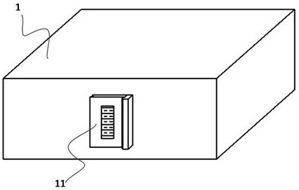
[0066] This embodiment provides a hot-swap-based automatic detachable split chassis system, including: several chassis units 1 and a controller 2 .

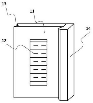
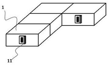
[0067] The chassis units 1 are independent of each other. At least one connecting device 11 is arranged on the chassis unit 1 , and a data interface device 12 is arranged in the connecting device 11 . The cabinet units 1 are connected to each other by connection means 11 .

[0068] The chassis unit 1 is a single box body, and the chassis unit 1 may also include a cooling device, an installation opening, etc., and the cooling module may be a fan or an air outlet for heat dissipation of the chassis unit 1 . The installation port is used for installing or removing the devices in the case unit 1 .

[0069] The connecting device 11 further includes a locking device 14 , a locking interface 13 is provided on one side of the connecting device 11 , and the locking device 14 is used for locking with the locking interface 13 . The locki...

Embodiment 2

[0115] This embodiment is a method embodiment of the first embodiment above.

[0116] A working method of a hot-swap-based automatic disassembly split chassis system, comprising:

[0117] The main chassis unit 1 and the auxiliary chassis unit 1 are connected to each other through a connecting device 11 .

[0118] The functional modules in the main chassis unit 1 exchange data with the functional modules in the auxiliary chassis unit 1 through the data interface device 12 of the connection device 11 .

[0119] If the user needs to use part of the functions of the chassis unit 1 , the controller 2 provides the user with a choice of the chassis unit 1 .

[0120] The controller 2 outputs unlocking signals to the locking devices 14 of other cabinet units 1 according to the cabinet unit 1 selected by the user.

[0121] The locking device 14 that receives the unlocking signal is unlocked, and the corresponding chassis unit 1 is disengaged.

[0122] As a preferred mode of the present...


PUM


Abstract

The invention discloses an automatic disassembly split type case system based on hot plug and a working method. The automatic disassembly split type case system comprises a plurality of case units anda controller; at least one connecting device is arranged on each case unit, and a data interface device is arranged in the connecting device; the case units are connected with each other through theconnecting devices; each connecting device further comprises a locking device, a locking connector is arranged on one side of the connecting device, the locking device is connected with the controller, the controller outputs a locking signal and / or an opening signal to the locking device, and the locking device locks and / or releases the locking interface according to the locking signal and / or theopening signal; after the connecting devices are connected with each other, the data interface devices are connected with each other, and the connected data interface devices are used for informationtransmission; at least one functional module of a computer is integrated in each case unit, the functional module is a hardware module of the computer, and the hardware module of the computer is divided according to functions and serves as a functional module for calculation.

Description

technical field [0001] The invention relates to the field of computer cases, in particular to a hot-plug-based automatic detachable split case system and a working method. Background technique [0002] A computer, commonly known as a computer, is an electronic computing machine used for high-speed computing. It can perform numerical calculations, logical calculations, and has storage and memory functions. It is a modern intelligent electronic device that can run according to the program and process massive data automatically and at high speed. Composed of hardware systems and software systems, computers without any software installed are called bare metal. It can be divided into five categories: supercomputers, industrial control computers, network computers, personal computers, and embedded computers. More advanced computers include biological computers, photonic computers, and quantum computers. [0003] The chassis of an existing computer is generally integrated as a wh...

Claims


Application Information

Patent Timeline
Patent Type & Authority Patents(China)
IPC IPC(8): G06F1/18G06F1/20G06F13/40
CPCG06F1/182G06F1/20G06F13/4081
Inventor 刘玉利赵承滨
Owner HARBIN UNIV
Why Eureka
Try Eureka