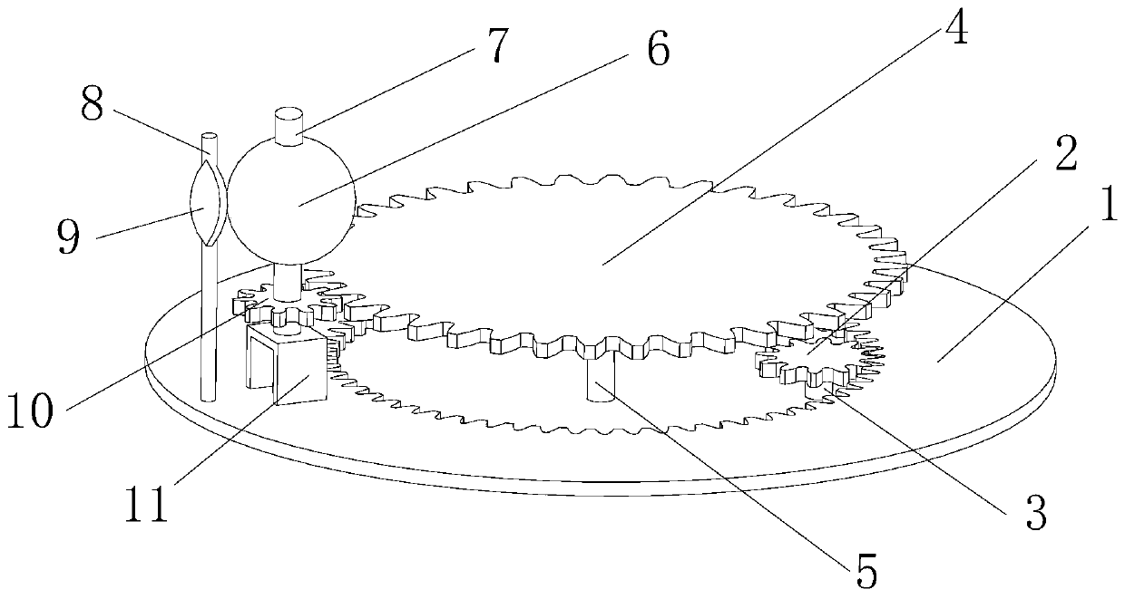
Device and method for plating film on curved surface material
A technology of coating device and curved surface is applied in metal material coating process, sputtering coating, ion implantation coating, etc., to achieve the effect of easy large-area production and simple device structure
- Summary
- Abstract
- Description
- Claims
- Application Information
AI Technical Summary
Problems solved by technology
Method used
Image
Examples
Embodiment 1
[0028] The shape of the curved surface to be plated is spherical, and the shape of the film thickness correction plate is as follows: figure 2 shown. First, the trimmed film thickness correction plate 9 is installed directly in front of the fixed frame 6 of the plated sample, and then the sample to be plated is installed horizontally on the fixed frame.
[0029] 1. Start vacuuming with a vacuum pump to 1.0×10 -3 Pa, and then filled with argon to raise the pressure to 0.7Pa.
[0030] 2. Turn on the sputtering power supply and perform pre-sputtering on the target. During the pre-sputtering, the target is away from the surface of the sample. By rotating the controller, the revolving device of the plated sample holder 6 is rotated to the front of the target, and then the revolving rotation is stopped. Start the rotation device of the fixed frame of the sample to be plated, so that the sample to be plated has been rotating directly in front of the target.
[0031] 3. Set the p...
Embodiment 2
[0036] The shape of the surface to be plated is a double sphere, and the shape of the film thickness correction plate is as follows: image 3 shown. The shape of the curved surface to be plated is spherical, and the shape of the film thickness correction plate is as follows: figure 2 shown. First, the trimmed film thickness correction plate 9 is installed directly in front of the fixed frame 6 of the plated sample, and then the sample to be plated is installed horizontally on the fixed frame.
[0037] 1. Start vacuuming with a vacuum pump to 1.0×10 -3 Pa, and then filled with argon to raise the pressure to 0.3Pa.
[0038] 2. Turn on the sputtering power supply and perform pre-sputtering on the target. During the pre-sputtering, the target is away from the surface of the sample. By rotating the controller, the revolving device of the plated sample holder 6 is rotated to the front of the target, and then the revolving rotation is stopped. Start the rotation device of the f...
Embodiment 3
[0044] The shape of the curved surface to be plated is a double sphere with a small top and a large bottom, and the shape of the film thickness correction plate is as follows: Figure 4shown. First, the trimmed film thickness correction plate 9 is installed directly in front of the fixed frame 6 of the plated sample, and then the sample to be plated is installed horizontally on the fixed frame.
[0045] 1. Start vacuuming with a vacuum pump to 1.0×10 -3 Pa, and then filled with argon to raise the pressure to 0.5Pa.
[0046] 2. Turn on the sputtering power supply and perform pre-sputtering on the target. During the pre-sputtering, the target is away from the surface of the sample. By rotating the controller, the revolving device of the plated sample holder 6 is rotated to the front of the target, and then the revolving rotation is stopped. Start the rotation device of the fixed frame of the sample to be plated, so that the sample to be plated has been rotating directly in fr...
PUM
 Abstract
Description
Claims
Application Information
 - R&D
- Intellectual Property
- Life Sciences
- Materials
- Tech Scout
- Unparalleled Data Quality
- Higher Quality Content
- 60% Fewer Hallucinations
Browse by: Latest US Patents, China's latest patents, Technical Efficacy Thesaurus, Application Domain, Technology Topic, Popular Technical Reports.
© 2025 PatSnap. All rights reserved.Legal|Privacy policy|Modern Slavery Act Transparency Statement|Sitemap|About US| Contact US: help@patsnap.com


