
Radiated spurious test method, device and system

A test method and stray technology, applied in the field of communication, can solve the problems of long testing time, inability to realize batch testing of production lines, and inability to cover machines, etc., to reduce testing time, fast radiation stray testing, and realize batch testing. Effect

Active Publication Date: 2019-12-20
OPPO CHONGQING INTELLIGENT TECH CO LTD
View PDF5 Cites 2 Cited by
  • Summary
  • Abstract
  • Description
  • Claims
  • Application Information

AI Technical Summary

Problems solved by technology

However, the above-mentioned test methods have certain defects and deficiencies. For example, the traditional far-field test method and the radiation near-field test scheme both take a long time to test, and the test needs to build a large test space, which is expensive and can only be used for sampling testing. , the test cannot cover the defects of every machine
However, the method of compressed far-field testing has the disadvantages of requiring multi-point testing, a single test takes a relatively long time, and cannot achieve batch testing on the production line.

Method used


Image

  • Radiated spurious test method, device and system
  • Radiated spurious test method, device and system
  • Radiated spurious test method, device and system

Examples


Embodiment Construction

[0035] Example embodiments will now be described more fully with reference to the accompanying drawings. Example embodiments may, however, be embodied in many forms and should not be construed as limited to the examples set forth herein; rather, these embodiments are provided so that this disclosure will be thorough and complete and will fully convey the concept of example embodiments to those skilled in the art. The described features, structures, or characteristics may be combined in any suitable manner in one or more embodiments.

[0036] Furthermore, the drawings are merely schematic illustrations of the present disclosure and are not necessarily drawn to scale. The same reference numerals in the drawings denote the same or similar parts, and thus repeated descriptions thereof will be omitted. Some of the block diagrams shown in the drawings are functional entities and do not necessarily correspond to physically or logically separate entities. These functional entities ...


PUM


Abstract

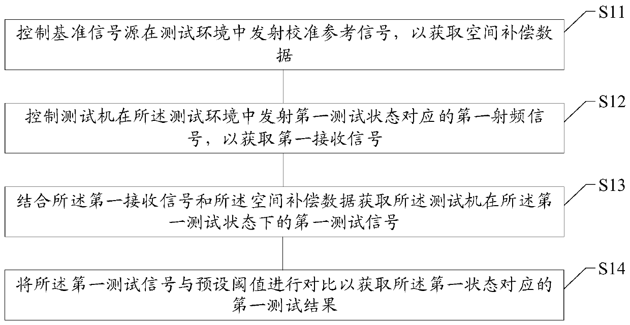
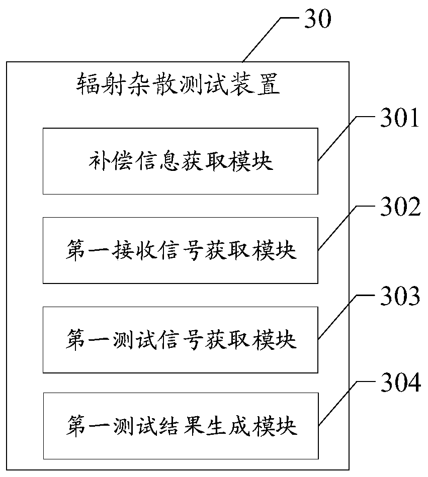
The invention relates to the technical field of communication, in particular to a radiated spurious test method, a radiated spurious test device, a radiated spurious test system, a computer readable medium and electronic equipment. The method comprises the following steps: controlling a reference signal source to transmit a calibration reference signal in a test environment so as to obtain space compensation data; controlling a test machine to transmit a first radio frequency signal corresponding to a first test state in the test environment so as to obtain a first receiving signal; acquiringa first test signal of the test machine in the first test state in combination with the first receiving signal and the spatial compensation data; and comparing the first test signal with a preset threshold to obtain a first test result corresponding to the first state. According to the scheme of the invention, the method can achieve the quick radiated spurious testing of the terminal equipment based on the near-field coupling principle, reduces the testing time, can cover more testing machines, and achieves the batch testing.

Description

technical field [0001] The present disclosure relates to the technical field of communications, and in particular to a radiation spurious testing method, a radiation spurious testing device, a radiation spurious testing system, a computer-readable medium, and an electronic device. Background technique [0002] The Radiated Spurious Emission (RES) test is an important test item in the certification of electronic equipment such as IT products, AV products, home appliances and wireless products. [0003] The prior art mainly includes: traditional far-field test (DFF, Direct Far Field), compact far-field test (IFF, Indirect Far Field) and radiation near-field test methods when performing radiation spurious test. However, the above-mentioned test methods have certain defects and deficiencies. For example, the traditional far-field test method and the radiation near-field test scheme both take a long time to test, and the test needs to build a large test space, which is expensive ...

Claims


Application Information

Patent Timeline
Patent Type & Authority Applications(China)
IPC IPC(8): H04B17/10H04B17/20H04B17/11
CPCH04B17/10H04B17/20H04B17/11
Inventor 周意保
Owner OPPO CHONGQING INTELLIGENT TECH CO LTD
Learn More