Transmitter combination rack and application method thereof

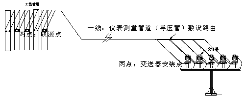
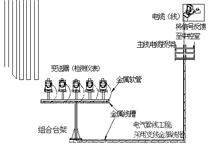
A transmitter and bench technology, which is applied in the field of transmitter combination bench, can solve the problems of difficult layout of instrument measurement pipelines and electrical pipelines, inconvenient construction and operation of construction workers, and poor operation and maintenance environment for production personnel. The effect of good visual quality of piping, saving project cost and good visual quality

Pending Publication Date: 2019-12-20
SHANGHAI BAOYE GRP CORP
View PDF0 Cites 0 Cited by
  • Summary
  • Abstract
  • Description
  • Claims
  • Application Information

AI Technical Summary

Problems solved by technology

[0003] Due to dense process pipelines, many types of media, and a large number of detection instruments, in areas where energy media are concentrated, various media pipeline facilities are densely distributed, and the space is limited. According to the existing construction and installation methods, instruments measure pipelines and electrical pipelines. Due to the limited space, the layout is very difficult, the construction operation of the construction workers is extremely inconvenient, and the operation efficiency is low. At the same time, it will also lead to the problem that the production personnel will have a relatively poor operation and maintenance environment in the future.

Method used


Image

  • Transmitter combination rack and application method thereof
  • Transmitter combination rack and application method thereof
  • Transmitter combination rack and application method thereof

Examples


Embodiment Construction

[0033] The present invention is further illustrated below by specific examples.

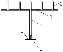
[0034] like figure 1 As shown, a combined transmitter stand includes a column 1, a mounting base 2, a cross arm 3, a transmitter mounting bracket 4 and a reinforced side plate 5; wherein the column 1 is vertically arranged on the mounting base 2, wherein , the lower part of the column 1 is connected with the inside or the side of the installation base 2, and the top of the column 1 is horizontally provided with a cross arm 3, wherein the top of the column 1 is connected with the bottom of the cross arm 3, and the transmission mounting bracket 4 has multiple , which are arranged on the cross arm 3 at intervals and arranged in sequence, and the interval distance is determined according to the overall size of the transmitter; there is a reinforcing side plate 5 surrounding the bottom of the column 1 and the installation base 2; in the above structure, the installation Between the base 2 and the col...


PUM


Abstract

The invention relates to the field of industrial equipment installation, in particular to a transmitter combination rack and an application method thereof. The transmitter combination rack is characterized by comprising a vertical post, an installation base, a cross arm, transmitter installation supports and reinforcement side plates, wherein the vertical post is vertically arranged on the installation base, a lower part of the vertical post communicates with the interior or a side part of the installation base, the cross arm is horizontally arranged at the top of the vertical post, the top ofthe vertical post communicates with the bottom of the cross arm, a plurality of transmitter installation supports are arranged on the cross arm at intervals and are sequentially arranged, the spacingdistance is determined according to the appearance size of a transmitter, and the reinforcement side plates are arranged between the bottom of the vertical post and the installation base in an encircling way. In the structure, penetrating cavities are enabled to be formed between the installation base and the vertical post, between the vertical post and the cross arm and between the cross arm andthe transmitter installation support so as to achieve a cable laying installation path. By the transmitter combination rack, the engineering quality can be improved, the quality risks that a cable ina pipe is scratched and insulation is damaged during laying of a cable penetrating pipe are prevented, and the integral construction of engineering is excellent in perceptual quality.

Description

technical field [0001] The invention relates to the field of industrial equipment installation, in particular to a transmitter combined stand and a use method thereof. Background technique [0002] In the automation instrument installation project, many detection instruments are installed on site as the "eyes and ears" of the operators to detect the operating conditions of each system, so as to monitor the economical and safe operation of the system. Each source point on the on-site process facility corresponds to an automatic detection instrument. From the source point to the detection instrument (transmitter), it is necessary to configure a measuring pipeline-a pressure guide tube to obtain the medium condition and transmit it to the transmitter. The transmitter obtains the medium information and then converts it into a signal source to feed back the signal to the central control room through the configured electrical cable, so as to realize the role of "eyes and ears" on ...

Claims


Application Information

Patent Timeline
IPC IPC(8): H02B5/02H02G3/04H02G1/08
CPCH02B5/02H02G3/045H02G1/08
Inventor 邱辉侯振峰杨松景戚凯
Owner SHANGHAI BAOYE GRP CORP
Why Eureka
Try Eureka