Herringbone gear system dynamic response calculation method under basic swing condition

A technology of herringbone gear and calculation method, applied in the field of dynamic analysis, can solve the problem that the fixed stiffness model cannot fully reflect the dynamic characteristics of the sliding bearing, and achieve the effect of rapid calculation analysis and simplified model

Active Publication Date: 2019-12-20
NORTHWESTERN POLYTECHNICAL UNIV
View PDF10 Cites 0 Cited by
  • Summary
  • Abstract
  • Description
  • Claims
  • Application Information

AI Technical Summary

Problems solved by technology

At present, in the research of gear transmission system, the supporting function of the sliding bearing is usually simplified to an eight-parameter constant stiffness and constant damping model, while the supporting function of the lubricating oil film of the sliding bearing is very complicated, especially under complex working conditions , the traditional constant stiffness model cannot fully reflect the dynamic characteristics of the sliding bearing, and it is urgent to accurately account for the nonlinear oil film force of the sliding bearing in the gear system, and there are few reports in the relevant literature; In the research on the dynamics of the gear system of the characteristics, most of the research objects of the literature are spur gear pairs, and there are few studies on the herringbone gear transmission system supported by sliding bearings, and the marine gear transmission system is mainly herringbone gears. It is necessary to Directly study the dynamic behavior of the herringbone gear; 3. During the movement of the foundation, it is inevitable to produce a swing motion, and its dynamic excitation will be transmitted to the sliding bearing through the foundation, and then transmitted to the herringbone gear transmission system. Dynamic behavior and bearing safety have complex effects, and existing research usually ignores the influence of foundation swing

Method used


Image

  • Herringbone gear system dynamic response calculation method under basic swing condition
  • Herringbone gear system dynamic response calculation method under basic swing condition
  • Herringbone gear system dynamic response calculation method under basic swing condition

Examples


Embodiment Construction

[0017] The following will clearly and completely describe the technical solutions in the embodiments of the present invention with reference to the accompanying drawings in the embodiments of the present invention. Obviously, the described embodiments are only some, not all, embodiments of the present invention. Based on the embodiments of the present invention, all other embodiments obtained by persons of ordinary skill in the art without making creative efforts belong to the protection scope of the present invention.

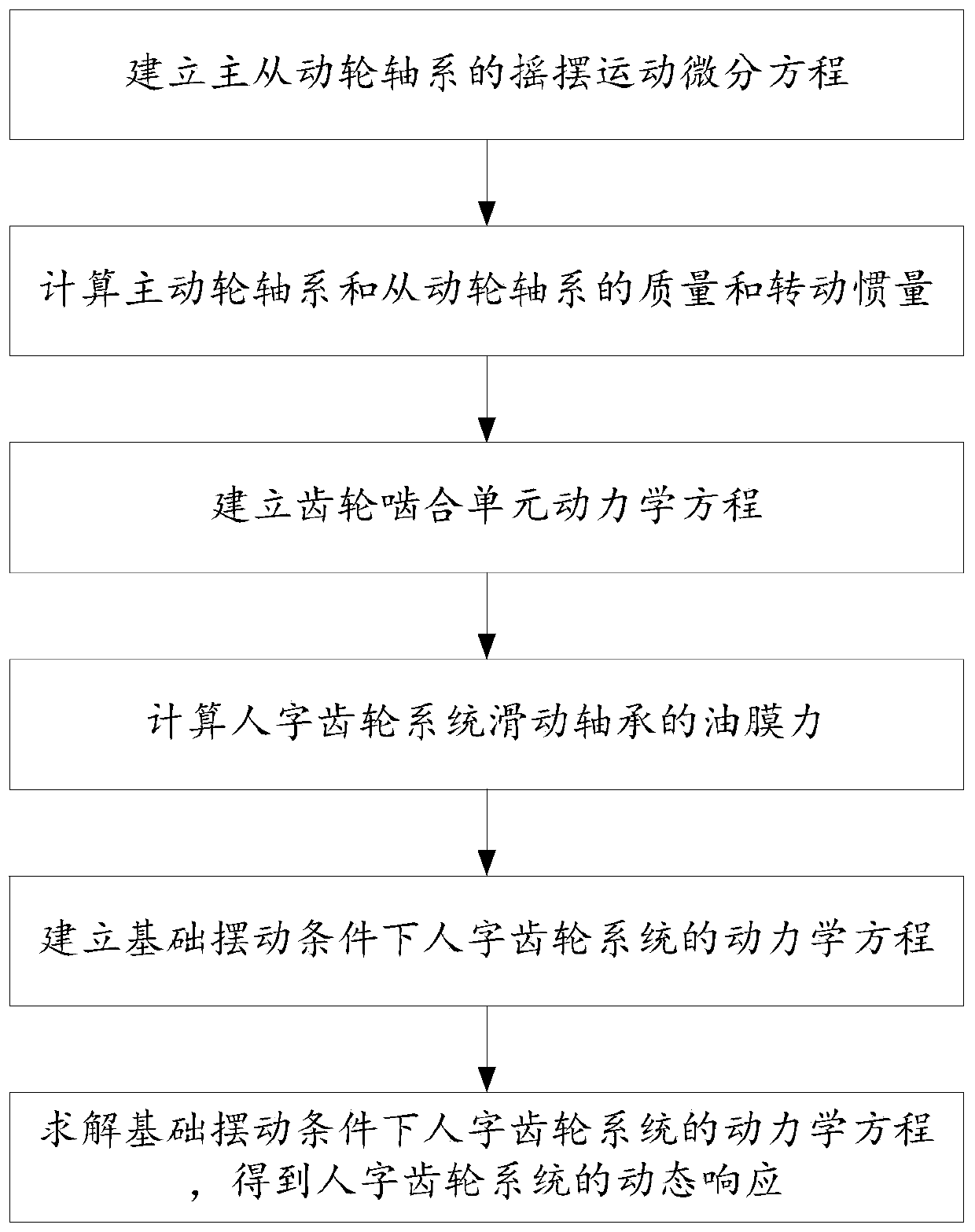
[0018] refer to figure 1 , the present invention provides a method for calculating the dynamic response of a herringbone gear system under basic swing conditions, the method comprising the following steps:

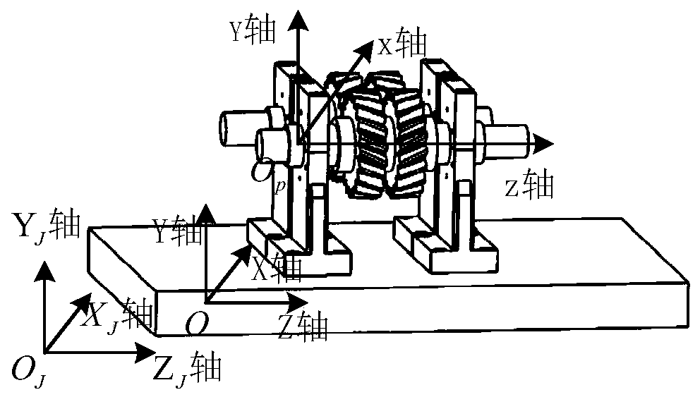
[0019] 1. Establish the basic swing coordinate system: such as figure 2 Shown, where, the coordinate system O J -X J Y J Z J is a fixed coordinate system, used to describe the relative position of the foundation, use (X J ,Y J ,Z J ) T Indicates;...


PUM


Abstract

The invention discloses a herringbone gear system dynamic response calculation method under a basic swing condition, and relates to the technical field of dynamic analysis, and the method considers the effects of three types of excitation in a model building process: herringbone gear time-varying meshing stiffness excitation; non-linear oil film force excitation of the sliding bearing; and a gyroscopic effect and an implicit inertia force generated by the system under a basic swinging condition. Meanwhile, the multi-excitation coupling kinetic equation is solved through a method of combining aNewmark method and a Newton-Raphson method. According to the method, the model is simplified as much as possible on the basis that the characteristics of the herringbone gear system are reserved, andit can be guaranteed that the herringbone gear system supported by the sliding bearing under the basic swing condition can be rapidly calculated and analyzed through the concentrated mass method.

Description

technical field [0001] The invention relates to the technical field of dynamic analysis, in particular to a method for calculating the dynamic response of a herringbone gear system under foundation swing conditions. Background technique [0002] Gear transmission system dynamics is a science that studies the dynamic characteristics of a gear system (including gears, rotors and bearings, etc.) under dynamic excitation. In recent years, with the deepening of my country's strategy of accelerating the construction of a maritime power, the need for further research on shipboard equipment has become increasingly urgent. As we all know, the herringbone gear transmission system supported by sliding bearings is widely used in ships, and its low noise, stability, safety and reliability are very important to the corresponding mechanical equipment. Therefore, it is of great significance to study the dynamic response of the sliding bearing supported herringbone gear system under the fou...

Claims


Application Information

Patent Timeline
Patent Type & Authority Applications(China)
IPC IPC(8): G06F17/50
CPCY02T90/00
Inventor 王海伟刘更刘岚吴立言焦阳
Owner NORTHWESTERN POLYTECHNICAL UNIV
Why Eureka
Try Eureka