
Segmental beam bottom mold system

A segmental beam and bottom mold technology, applied in molds, auxiliary molding equipment, ceramic molding machines, etc., can solve the problems of low utilization rate of bottom molds and high cost of templates, and achieve convenient application control, reasonable structure design, and bottom mold utilization. high rate effect

Inactive Publication Date: 2019-12-20
CHINA RAILWAY 16TH BUREAU GRP CO LTD +1
View PDF2 Cites 1 Cited by
  • Summary
  • Abstract
  • Description
  • Claims
  • Application Information

AI Technical Summary

Problems solved by technology

[0003] In the prior art, when designing the segmental beam bottom formwork of such a large-span variable cross-section continuous beam, the bottom formwork is usually designed separately according to the height or inclination of the segment, resulting in low utilization of the bottom formwork and the formwork high cost

Method used


Image

  • Segmental beam bottom mold system
  • Segmental beam bottom mold system
  • Segmental beam bottom mold system

Examples


Embodiment 1

[0027] This embodiment is used for segmental prefabrication of long-span variable-section continuous beams. The section height of long-span variable-section continuous beams changes along the longitudinal direction of the bridge, and the vertical height of the bottom of the beam body is in the shape of a parabola or arc along the longitudinal direction. The main advantages of using segmental prefabrication compared with traditional box girder are:

[0028] 1) The beam section is small in size and convenient for transportation, and general roads can meet the transportation requirements of segmental beams;

[0029] 2) The concrete shrinkage and creep of the segmental beam is small, and the line shape of the beam body does not change much after completion;

[0030] 3) Factory-like prefabricated production of segmental beams is convenient for production organization and overall construction quality control; centralized prefabricated production of segmental beams is beneficial to p...

Embodiment 2

[0034] see Figure 3-5 , the difference between this embodiment and embodiment 1 is:

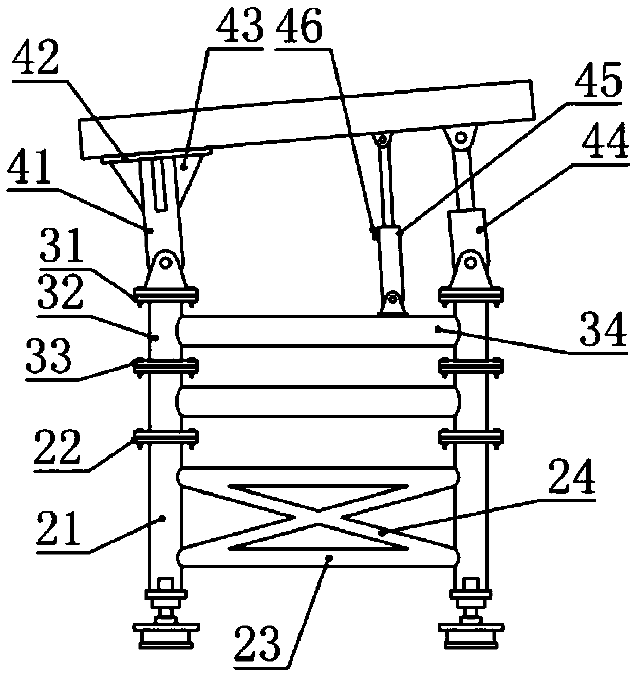
[0035] In this example, if figure 2 As shown, the base support 2 includes a column 21, a first connecting flange 22, a beam 23 and an X beam 24, the column 21 is provided with two, and the fine-tuning seat 1 is installed on the lower ends of the two columns 21, and the two columns The upper end of 21 is installed and fixed with the first connection flange 22 that is used for being connected and fixed with elevated bracket 3; Also installed and fixed with crossbeam 23 and X beam 24 between two described columns 21, specifically, the X beam 24 A crossbeam 23 is respectively arranged on the upper and lower sides, and the ends of the crossbeam 23 and the X-beam 24 are welded and fixed with the column 21 .

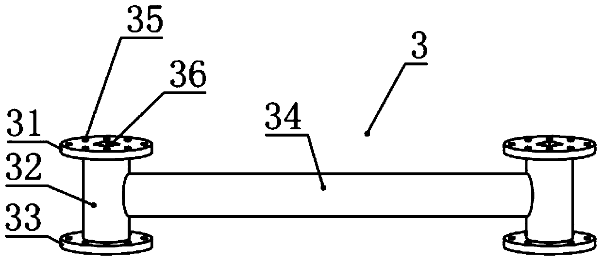
[0036] In this example, if figure 2 with 3 As shown, the elevated support 3 includes a second connection flange 31, a support beam 32, a third connection flange 33 and a tension beam 34, ...


PUM


Abstract

The invention relates to the field of segmental beams, in particular to a segmental beam bottom mold system. The system comprises a fine adjustment base, a foundation support, elevated supports, an adjusting device and a bottom mold. The lower end of the foundation support is provided with the fine adjustment base capable of being subjected to position adjusting relative to the foundation support,at least one elevated support is arranged on the upper end of the foundation support, the upper end of the elevated support on the uppermost is provided with the bottom mold through the adjusting device, and the adjusting device comprises a hydraulic telescopic cylinder used for carrying out angle fine adjustment on the bottom mold and a telescopic adjusting supporting rod for auxiliary supporting of the bottom mold. The segmental beam bottom mold system is reasonable in structural design, convenient to apply and control, capable of being stably regulated, high in bottom mold use rate, capable of reducing cost, suitable for the large-span segmental beam predication with the beam body bottom being in set height and also suitable for construction of segmental beams in various special shapes.

Description

technical field [0001] The invention relates to the field of segmental beams, in particular to a segmental beam bottom formwork system. Background technique [0002] At present, in the construction of cross-river or sea-crossing bridges, long-span variable-section continuous beams are often used due to their good mechanical properties and beautiful appearance. The section height of the long-span variable-section continuous beam changes along the longitudinal direction of the bridge, and the vertical height of the bottom of the beam body is in the shape of a parabola or an arc along the longitudinal direction. The short-line matching segmental beam prefabrication construction method is more and more applied to this type of long-span variable-section continuous beam due to its advantages such as short construction period on site, small impact on the environment and existing traffic, small safety risk, and reliable construction quality. Beam under construction. Because in the...

Claims


Application Information

Patent Timeline
Patent Type & Authority Applications(China)
IPC IPC(8): B28B7/22B28B17/00
CPCB28B7/22B28B17/00
Inventor 孙星吴峰戴东利方志强王勇李满曹建春
Owner CHINA RAILWAY 16TH BUREAU GRP CO LTD
Learn More