
Multidirectional die-forging hydraulic press of novel structure

A multi-directional die forging technology with a new structure, applied in the direction of swage forging presses, forging presses, forging presses, etc., can solve the problem of affecting the quality of multi-directional die forgings, uneven wall thickness of die forgings, and inconvenient feeding and retrieving and other problems, to achieve the effect of convenient feeding and retrieving, reducing horizontal frame and saving time

Inactive Publication Date: 2019-12-20
SHANGHAI DIANJI UNIV
View PDF6 Cites 3 Cited by
  • Summary
  • Abstract
  • Description
  • Claims
  • Application Information

AI Technical Summary

Problems solved by technology

When the hydraulic press of this structure is performing multi-directional die forging, it needs a vertical mold clamping device, the most common of which is a three-flange valve body; during die forging, the vertical mold clamping device clamps the mold and puts the workpiece, because it is a vertical discharge , There must be a certain gap between the workpiece and the mold. The existence of the gap is easy to cause material deviation, which makes the wall thickness of the die forging uneven, thus affecting the quality of the multi-directional die forging; very inconvenient

Method used

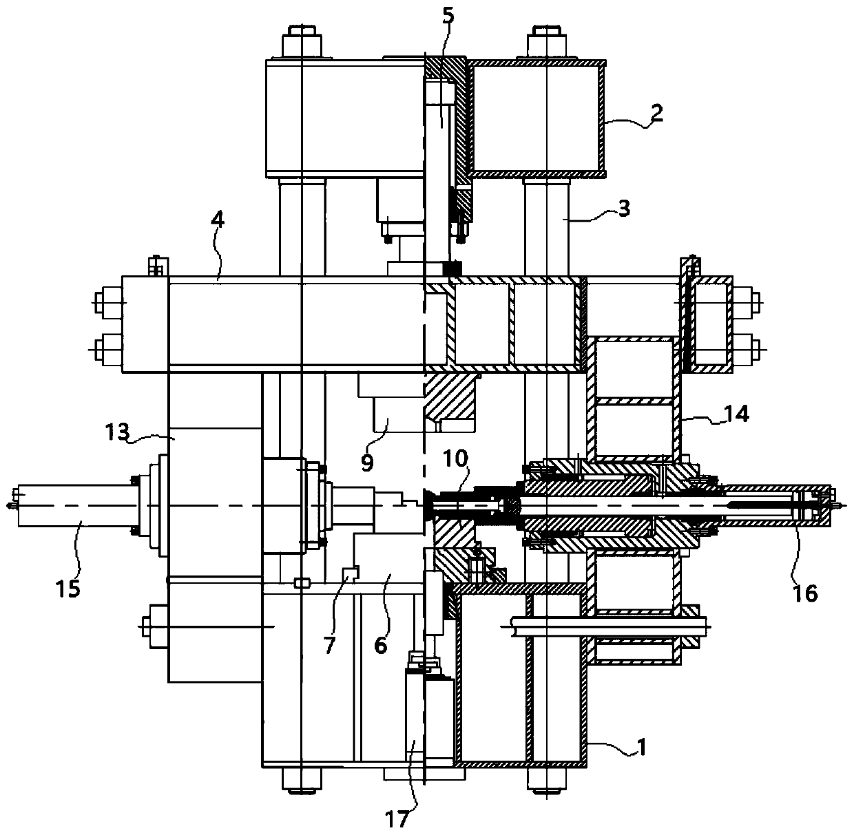
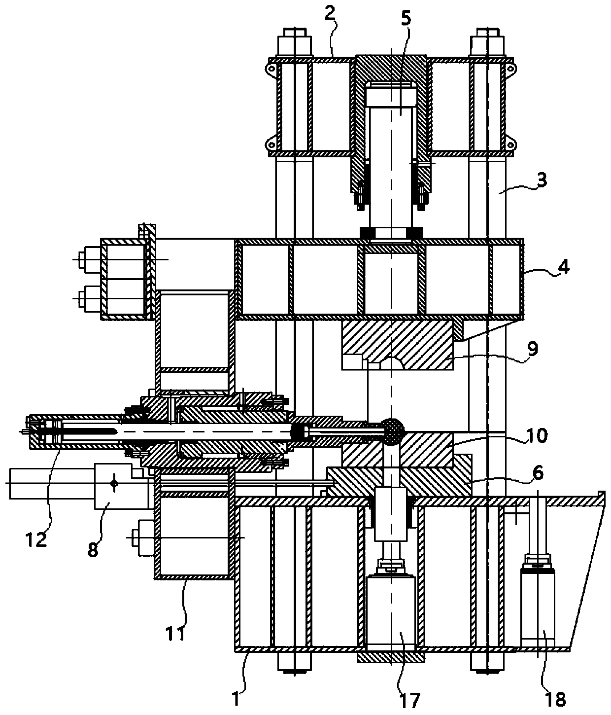

Image

  • Multidirectional die-forging hydraulic press of novel structure
  • Multidirectional die-forging hydraulic press of novel structure

Examples


Embodiment Construction

[0021] In order to make the technical means, creative features, goals and effects achieved by the present invention easy to understand, the present invention will be further elaborated below in conjunction with illustrations and specific embodiments.

[0022] like figure 1 , figure 2 As shown, the multi-directional die forging hydraulic press proposed by the present invention includes a lower beam 1, an upper beam 2 and a column 3, the lower beam is arranged horizontally, the upper beam is located above the lower beam, and is parallel to the lower beam, and a pair of columns are arranged. Between the lower beam and the upper beam, each column is vertically arranged and parallel to each other. The top of the column is fixedly connected with the upper beam, and the bottom end is fixedly connected with the lower beam. The main frame is composed of the upper beam, the lower beam and the column; it also includes activities Crossbeam 4, the movable crossbeam is positioned between ...


PUM


Abstract

The invention provides a multidirectional die-forging hydraulic press of a novel structure. The multidirectional die-forging hydraulic press comprises a lower cross beam, an upper cross beam and standcolumns. The lower cross beam is transversely arranged, and the upper cross beam is located above the lower cross beam and is parallel to the lower cross beam. One pair of stand columns is arranged and located between the lower cross beam and the upper cross beam, and the stand columns are vertically arranged and are parallel. The top ends of the stand columns are fixedly connected with the uppercross beam, and the bottom ends of the stand columns are fixedly connected with the lower cross beam. A main rack is formed by the upper cross beam, the lower cross beam and the stand columns. A movable cross beam is further included and located between the upper cross beam and the lower cross beam, and is parallel to the upper cross beam and the lower cross beam. A die assembling cylinder is mounted between the upper cross beam and the movable cross beam, and drives the movable cross beam to ascend and descend. A workbench is further included and mounted on the lower cross beam through a guide rail, the guide rail extends from the rear side of the lower cross beam to the front side of the lower cross beam, and a movable workbench cylinder is mounted on the lower cross beam; and a pistonrod of the movable workbench cylinder is connected with the workbench, and the movable workbench cylinder drives the workbench to move front and back.

Description

technical field [0001] The invention relates to forging equipment, in particular to a multi-directional die forging hydraulic press with a new structure. Background technique [0002] Multi-directional die forging has become the basis of major national economy industries such as machinery manufacturing, energy and electric power, petrochemical industry, iron and steel metallurgy, ship and vehicle, and also the foundation of national defense construction and other industries. The quality of forgings often determines the success or failure of equipment manufacturing . With the continuous development of forging technology, higher requirements are put forward for multi-directional die forging hydraulic presses. The forgings produced by the multi-directional die forging hydraulic press not only have complex shapes and meet the quality requirements, but also can improve forging production efficiency. One machine is multi-purpose, which can better meet the needs of the development...

Claims


Application Information

Patent Timeline
IPC IPC(8): B21J9/02B21J9/04B21J9/06
CPCB21J9/022B21J9/04B21J9/06
Inventor 任运来陈奕掌任杰牛龙江曹峰华
Owner SHANGHAI DIANJI UNIV
Learn More