Lifting type cleaning mechanism for optical part obtained after coating

A technology for cleaning mechanisms and parts, applied in the field of parts cleaning, can solve problems such as inability to guarantee the cleanliness of the workpiece surface, unfavorable procedures, workpiece rework, etc., and achieve the effects of convenient cleaning, time saving, fast cleaning and drying

Inactive Publication Date: 2019-12-20
扬州辰亚光学科技有限公司
View PDF7 Cites 4 Cited by
  • Summary
  • Abstract
  • Description
  • Claims
  • Application Information

AI Technical Summary

Problems solved by technology

Commonly used coating methods include vacuum coating (a type of physical coating) and chemical coating. In the production process of optical components, it needs to go through processes such as photolithography, coating, precision scribing, cleaning, and finished product inspection. The degree of cleaning before is not up to the standard, and the surface cleanliness of the workpiece cannot be guaranteed. In the subsequent inspection of finished products, the workpiece will be reworked or scrapped.
[0003] Most of the existing cleaning mechanisms use hanging baskets to store and clean parts. It is very convenient to clean, but it is not convenient for drying, which is not conducive to the subsequent process.

Method used


Image

  • Lifting type cleaning mechanism for optical part obtained after coating
  • Lifting type cleaning mechanism for optical part obtained after coating
  • Lifting type cleaning mechanism for optical part obtained after coating

Examples


Embodiment Construction

[0021] The technical solutions in the embodiments of the present invention will be clearly and completely described below in conjunction with the accompanying drawings in the embodiments of the present invention. Obviously, the described embodiments are only a part of the embodiments of the present invention, rather than all the embodiments. Based on the embodiments of the present invention, all other embodiments obtained by those of ordinary skill in the art without creative work shall fall within the protection scope of the present invention.

[0022] Unless the directions are defined separately, the up, down, left, right, front, back, inner, and outer directions referred to herein are all the up, down, left, right, front, and back in the drawings shown in the present invention. , Internal and external directions shall prevail, which shall be explained here.

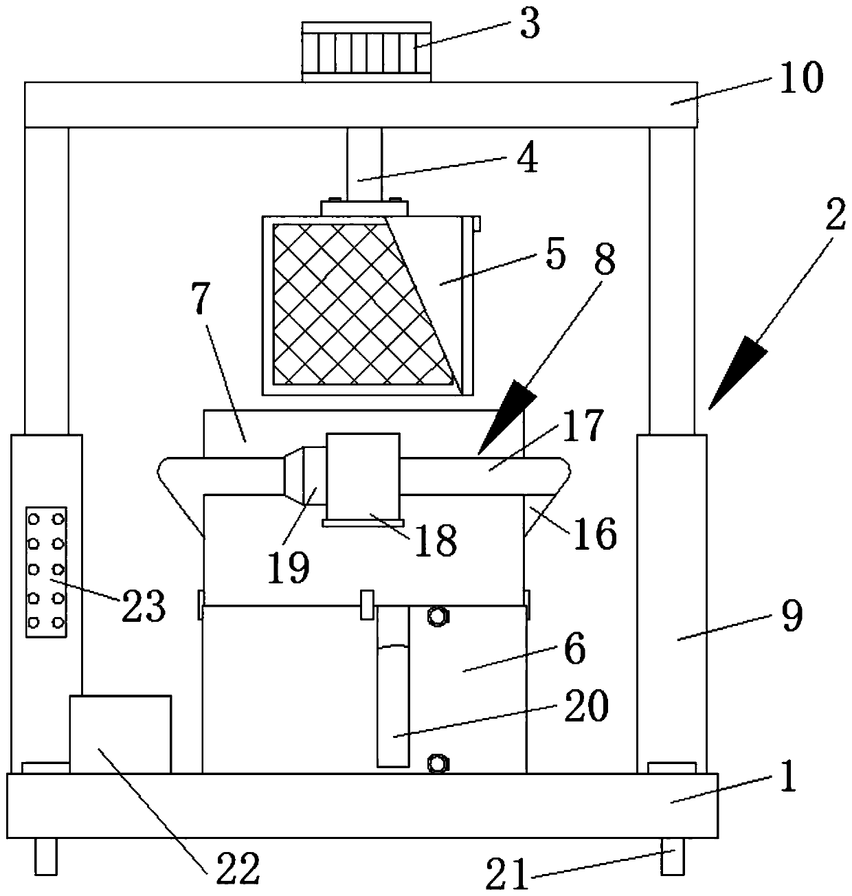
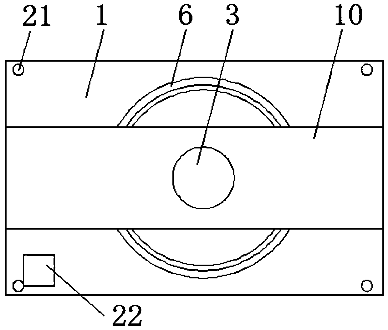
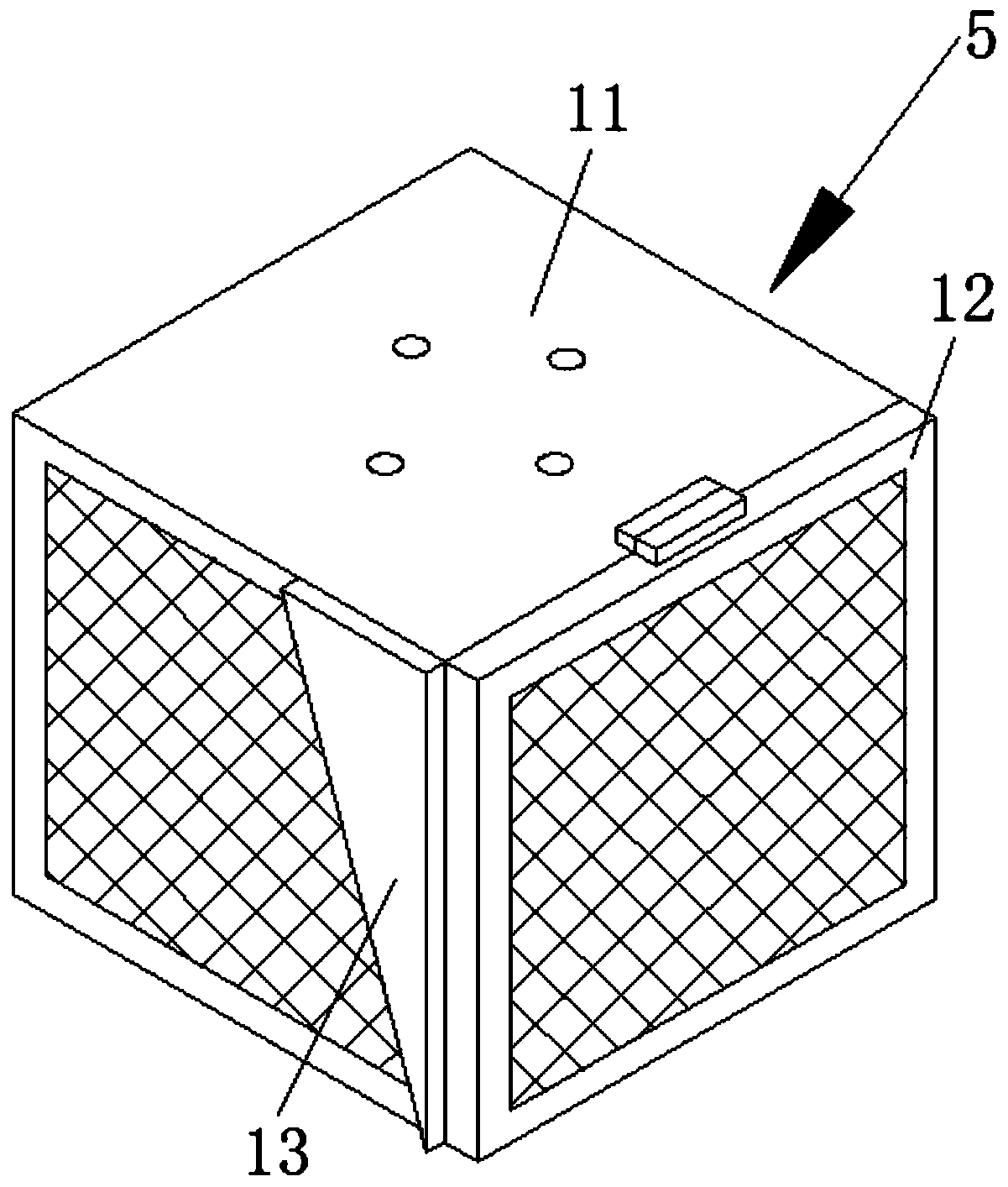
[0023] The present invention provides Figure 1-5 The illustrated lifting cleaning mechanism for optical components afte...


PUM


Abstract

The invention discloses a lifting type cleaning mechanism for an optical part obtained after coating. The lifting type cleaning mechanism comprises a workbench, a height adjusting device, a storage device and a drying device. The height adjusting device is welded to the top end of the workbench. A rotary motor is connected to the top end of a transverse plate of the height adjusting device througha screw. A rotary shaft is connected to an output shaft of the rotary motor through a coupling, and the lower half of the rotary shaft penetrates through a vertical through hole dug in the transverseplate. A round plate is welded to the bottom end of the rotary shaft. The storage device is connected to the round plate through a vertical bolt. A liquid storage bucket is arranged in a holding groove dug in the workbench. A protection device is arranged above the liquid storage bucket, and the drying device communicates with the periphery of the protection device. The height adjusting device comprises a vertical hydraulic rod and the transverse plate. Through the lifting type cleaning mechanism for the optical part obtained after coating, stable cleaning and drying can be conducted fast, and work efficiency is promoted.

Description

Technical field [0001] The invention belongs to the technical field of parts cleaning, and in particular relates to a lifting cleaning mechanism used for optical parts after coating. Background technique [0002] Optical coating refers to the process of coating a layer (or multiple layers) of metal (or medium) film on the surface of optical parts. The purpose of coating the surface of optical parts is to reduce or increase light reflection, beam splitting, color separation, light filtering, polarization and other requirements. Commonly used coating methods include vacuum coating (a kind of physical coating) and chemical coating. In the production process of optical parts, it needs to go through the process flow of photolithography, coating, precision scribing, cleaning and finished product inspection. The previous cleaning level is not up to the standard, and the surface cleanliness of the workpiece cannot be guaranteed. In the subsequent inspection of the finished product, the ...

Claims


Application Information

Patent Timeline
Patent Type & Authority Applications(China)
IPC IPC(8): B08B3/10F26B5/08F26B3/02B08B3/04F26B21/00
CPCB08B3/045F26B3/02F26B5/08F26B21/001F26B21/004
Inventor 戚志洋
Owner 扬州辰亚光学科技有限公司
Why Eureka
Try Eureka