Flue gas desulfurization device
A desulfurization device and flue gas technology, applied to the separation of dispersed particles, chemical instruments and methods, separation methods, etc., can solve the problems of insufficient flue gas desulfurization effect, insufficient contact between absorption liquid and flue gas, and high consumption of absorption liquid. , to achieve the effect of improving the desulfurization effect, improving the desulfurization effect, and improving the absorption effect
- Summary
- Abstract
- Description
- Claims
- Application Information
AI Technical Summary
Problems solved by technology
Method used
Image

Examples
Embodiment 1
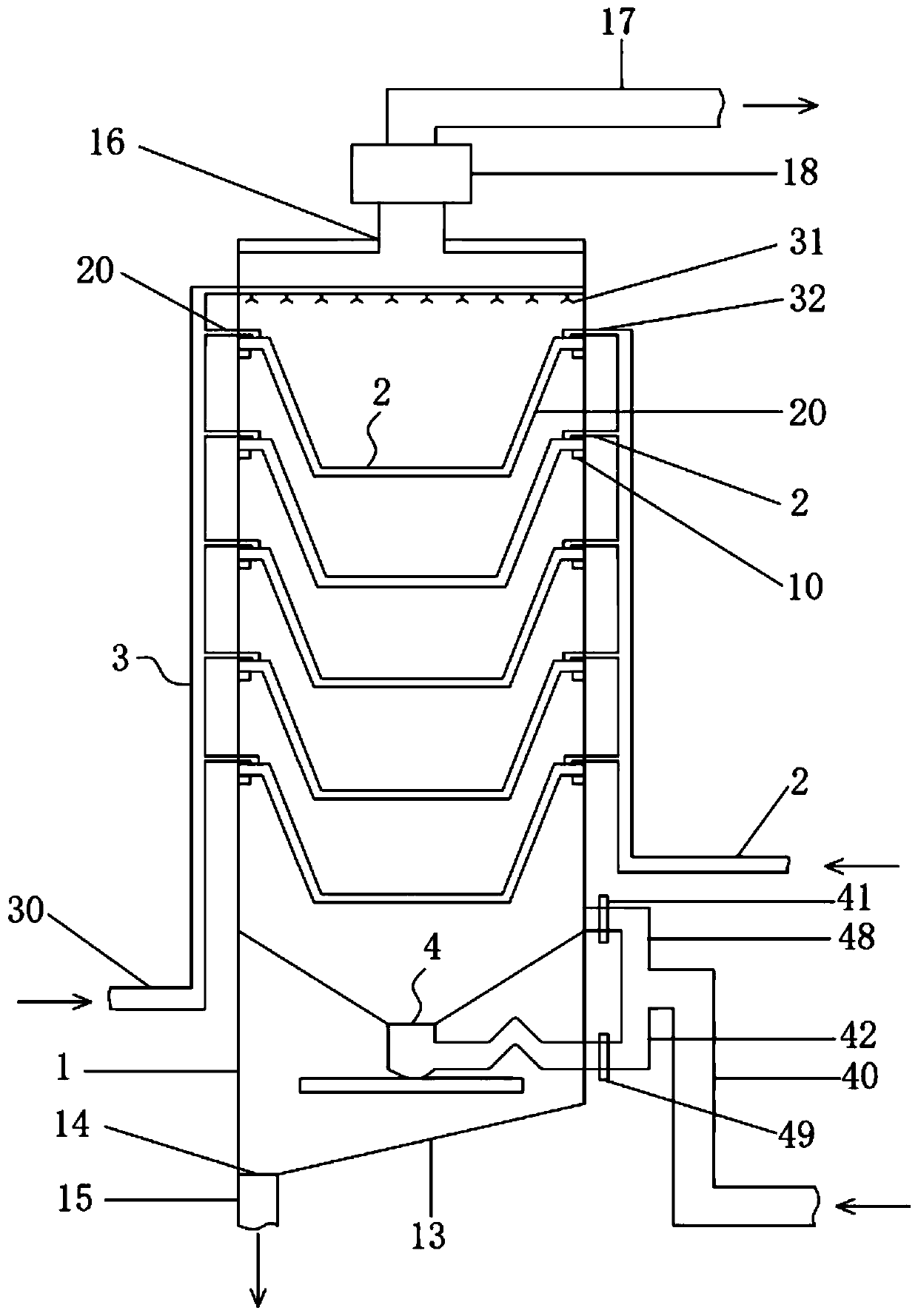
[0038] Such as figure 1 As shown, a flue gas desulfurization device in this embodiment includes: a desulfurization tower body 1, a wet filter assembly 2 arranged inside the desulfurization tower body 1, and a spray assembly 3 for supplying absorption liquid into the desulfurization tower body 1 And a gas distribution component 4 for delivering the flue gas to be treated to the desulfurization tower body 1;
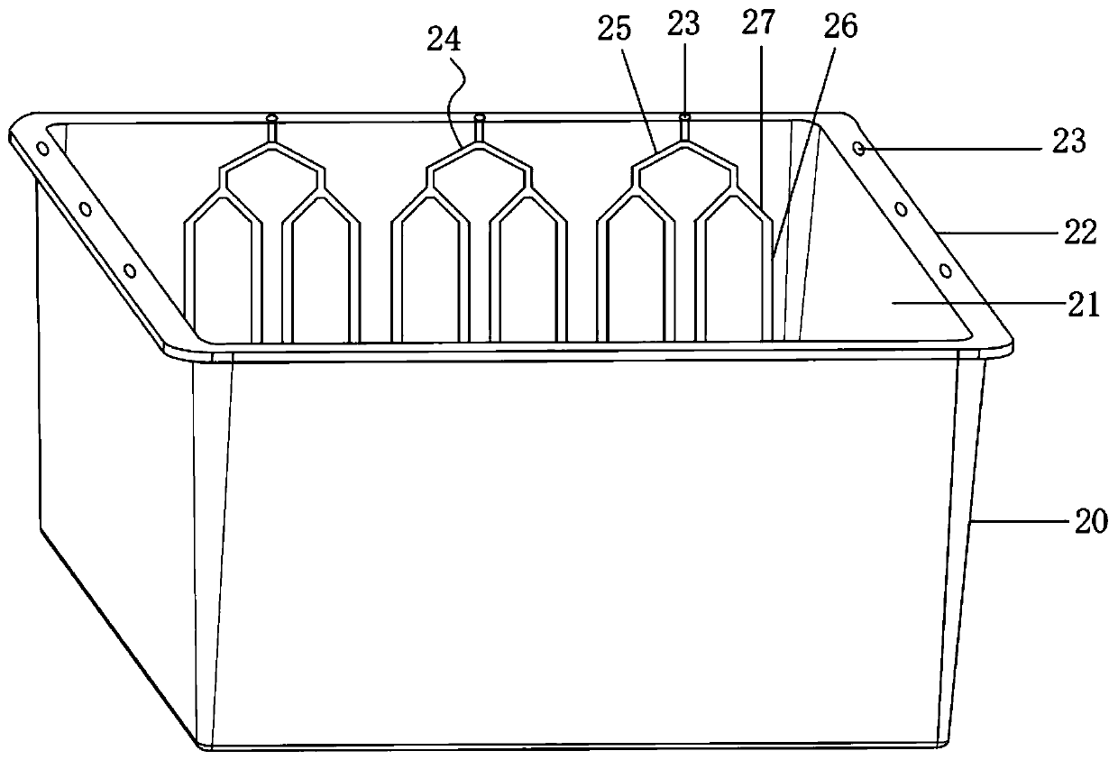
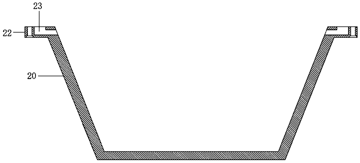
[0039] The wet filter assembly 2 includes several cassette filters 20 stacked along the height direction of the desulfurization tower body 1. The cassette filters 20 are in the shape of an inverted trapezoid with an inverted trapezoid cavity 21 inside, and the cassette filter The device 20 has a densely arranged microporous structure that runs through its body for the passage of smoke;
[0040] The air distribution assembly 4 includes an air inlet pipe 40 , a first air distribution pipe 41 and a second air distribution pipe 42 communicating with the air inlet pipe 40 , an...
Embodiment 2
[0045] On the basis of embodiment 1, more specifically, refer to Figure 7-8 , in this embodiment, the lower end of the adapter tube head 43 communicates with the inside of the liquid guide box 45 through a constricted tube 46 . The second air distribution pipe 42 is provided with a liquid blocking pipe section, which is an upwardly protruding inverted V-shaped pipe section 47 arranged in the middle of the second air distribution pipe 42 . The lower circular opening 440 of the cone air distribution cylinder 44 is smaller than its upper circular opening 441, and the outlet end of the first air distribution pipe 41 is connected to the side of the upper circular opening 441 of the cone air distribution cylinder 44, and the first air distribution pipe 41 The outlet end of the upper circular opening 441 is arranged along the tangential direction of the outer periphery.
[0046] The top of the cassette filter 20 is provided with a protruding edge 22 toward the outer periphery, and ...
Embodiment 3
[0051] This embodiment is a further embodiment on the basis of embodiment 2, refer to Figure 2-6 , wherein, the liquid guide groove 24 includes a liquid distribution groove section 25 and a drainage groove section 26, the liquid distribution groove section 25 is a tree-like bifurcated structure, the liquid inlet end of the upper part communicates with the liquid inlet hole 23, and the lower part of the tree-like bifurcation A plurality of branch streams 27 are formed, and the liquid outlets of the branch streams 27 are connected to a drainage groove segment 26 . The spray assembly 3 includes an infusion pipe 30, a spray head 31 communicated with the infusion pipe 30 and arranged above the wet filter assembly 2, a number of liquid distribution pipes 32 communicated with the infusion pipe 30, and a dropper connected to the outlet end of the liquid distribution pipe 32. A dripper is correspondingly provided above the liquid inlet hole 23 of each cartridge filter 20 . By setting...
PUM
 Abstract
Description
Claims
Application Information
 - R&D
- Intellectual Property
- Life Sciences
- Materials
- Tech Scout
- Unparalleled Data Quality
- Higher Quality Content
- 60% Fewer Hallucinations
Browse by: Latest US Patents, China's latest patents, Technical Efficacy Thesaurus, Application Domain, Technology Topic, Popular Technical Reports.
© 2025 PatSnap. All rights reserved.Legal|Privacy policy|Modern Slavery Act Transparency Statement|Sitemap|About US| Contact US: help@patsnap.com