
Multifunctional continuous projectile motion experiment instrument

A continuous and multi-functional technology, applied in the direction of instruments, teaching models, educational appliances, etc., can solve the problems of waste, cannot be recorded in a more direct way, and cannot display the initial speed visually and intuitively, so as to achieve easy reading, The effect of expanding the learning space

Pending Publication Date: 2019-12-17
EAST CHINA NORMAL UNIVERSITY
View PDF0 Cites 4 Cited by
  • Summary
  • Abstract
  • Description
  • Claims
  • Application Information

AI Technical Summary

Problems solved by technology

[0006] 1. This method will not be able to record the trajectory of the object when it is thrown flat in a more direct way, but needs to use the gear lever to record the points on the trajectory of the ball, but the trajectory of the ball is recorded on the coordinate paper point, the ball has completed the collision with the gear lever, and is no longer a point on the trajectory of the ball when it is thrown flat. Although it is possible to determine an average position as a certain point on the trajectory through multiple experiments, the time For the extremely precious classroom, this is undoubtedly a waste, and the determined point is also an approximate point taken during multiple collisions, and may not be a point on the trajectory of the ball when it is thrown flat.
[0007] 2. This method cannot completely and continuously present the trajectory of the object in flat throwing motion, which is not conducive to students quickly constructing a physical model of flat throwing motion
[0008] 3. This approach cannot visualize and quantitatively calculate the initial velocity of the unknown initial position and the known initial position
[0009] 4. This approach cannot be extended to projectile sports with different inclination angles, which is not conducive to students expanding from flat throwing sports to other projectile sports

Method used


Image

  • Multifunctional continuous projectile motion experiment instrument
  • Multifunctional continuous projectile motion experiment instrument
  • Multifunctional continuous projectile motion experiment instrument

Examples


Embodiment Construction

[0068] In conjunction with the following specific embodiments and accompanying drawings, the invention will be further described in detail. The process, conditions, experimental methods, etc. for implementing the present invention, except for the content specifically mentioned below, are common knowledge and common knowledge in this field, and the present invention has no special limitation content.

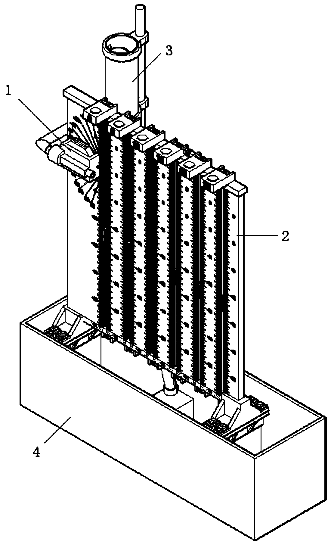
[0069] Such as Figure 3 to Figure 19 As shown, the multifunctional continuous projectile motion tester in this embodiment includes a water outlet pipe fixing block, a trajectory marking plate, a constant flow device and a base water storage box. The fixed block of the water outlet pipe is adsorbed on the track marking plate by a strong magnetic material, and its position can be changed; the track marking plate is placed on the base support frame of the base water storage box; the constant flow device is arranged behind the periphery of the base water storage box, also Located b...


PUM


Abstract

The invention provides a multifunctional continuous projectile motion experiment instrument which comprises a water outlet pipe fixing block, a track marking plate, a constant flow device and a base water storage box, wherein the water outlet pipe fixing block is adsorbed on the track marking plate through a strong magnetic material and can be freely moved; the track marking plate is put in the base water storage box; and the constant flow device is arranged behind the base water storage box and is positioned behind the track marking plate. The multifunctional continuous projectile motion experiment instrument has the advantages that the operation is simple and convenient; experiment data can be easily obtained; the data processing is convenient and fast; the horizontal projectile motion can be studied; and the oblique upward projectile motion and the oblique downward projectile motion can also be studied.

Description

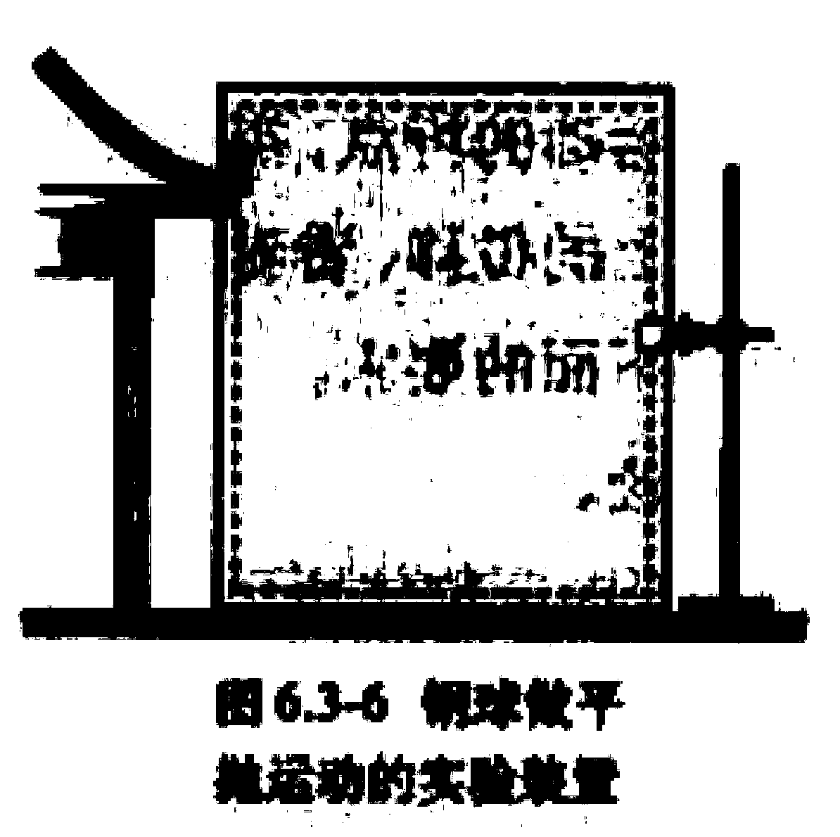
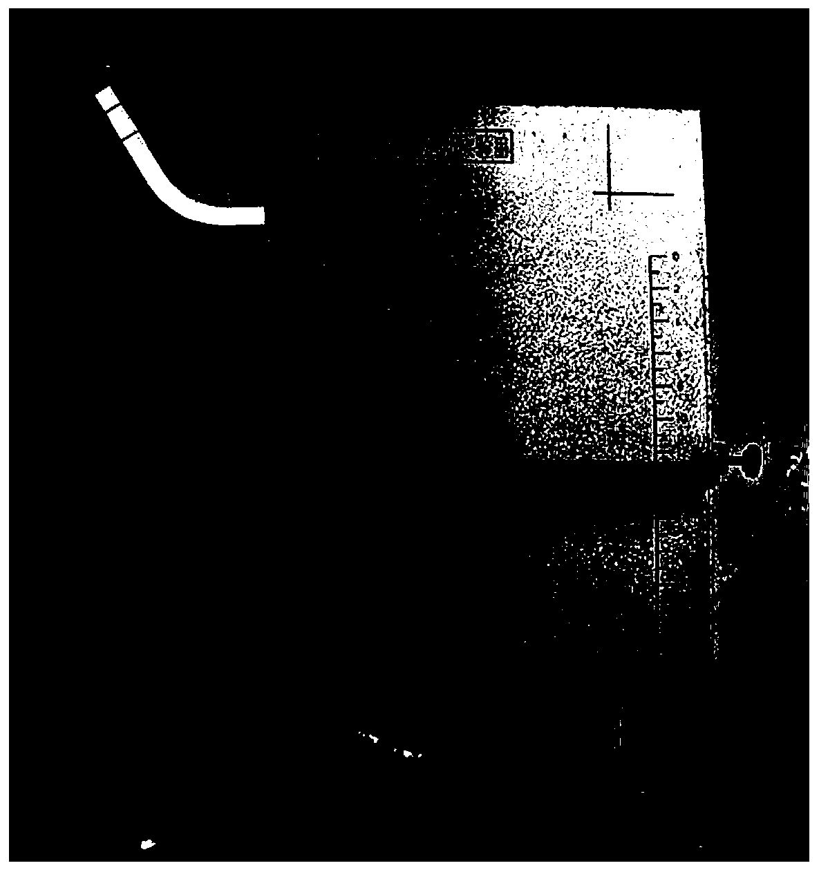
technical field [0001] The invention relates to the technical field of physical demonstration experiment instruments, in particular to a multifunctional continuous projectile motion experiment instrument. Background technique [0002] The flat throwing movement is an important teaching content in the compulsory 2 of high school physics. At present, the experimental experimental devices used to demonstrate the motion of flat throw usually include the following methods: [0003] Such as Figure 1-Figure 2 As shown in the figure, the conventional flat throwing motion demonstration experimental apparatus is formed by using the chute at the end tangent level, whiteboard, carbon paper, coordinate paper and gear bar. Each time the ball is released from rest at the same height, a point is taken for several experiments, and the position of the lever is constantly changed, so that the ball collides with the lever, and the positions where the ball falls at different heights are record...

Claims


Application Information

Patent Timeline
IPC IPC(8): G09B23/10
CPCG09B23/10
Inventor 林亚萍景培书余登炯
Owner EAST CHINA NORMAL UNIVERSITY
Learn More