Waste heat recovery system of flue gas in power plant and recovery method thereof

A flue gas waste heat and recovery system technology, applied in the field of flue gas waste heat treatment, can solve the problem of low heat transfer coefficient of one-way fluid in water-cooled heat exchangers, which is difficult to adapt to boiler operation and coal type change factors, heat exchangers and water circulation Problems such as high system cost, to achieve the effect of cheap phase change point adjustment, avoiding flue gas dew point, and reducing system life

Pending Publication Date: 2019-12-17
JILIN JICHANG ELECTRIC POWER CO LTD +1
View PDF0 Cites 0 Cited by
  • Summary
  • Abstract
  • Description
  • Claims
  • Application Information

AI Technical Summary

Problems solved by technology

[0003] ①. The water-cooling method mainly relies on the sensible heat of water, so the temperature rise of water directly affects the area of ​​heat exchanger and the amount of circulating water, and also affects the shape of water pipes and circulating pumps;
[0004] ②. The dew point caused by the water-cooled heat exchanger in the low-temperature section causes serious compaction on the surface of the heat exchanger, which directly affects the normal operation of the boiler and causes a decrease in power generation;
[0005] ③. The one-way fluid heat transfer coefficient of the water-cooled heat exchanger is low, especially the increase of internal scale, which leads to the decline of the heat transfer performance of the heat exchanger year by year;
[0006] ④. The heat transfer coefficient of the water-cooled heat exchanger is generally 30-40W / m 2 K, leading to high cost of heat exchanger and water circulation system
[0007] ⑤. The water-cooled method has poor adjustment ability and is difficult to adapt to the influence of boiler operation and coal type change factors

Method used


Image

  • Waste heat recovery system of flue gas in power plant and recovery method thereof

Examples


Embodiment Construction

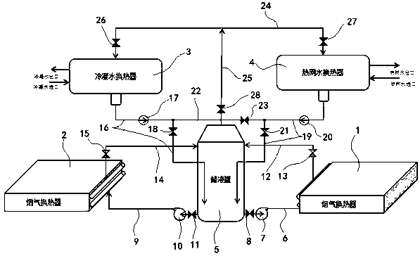
[0026] attached by figure 1 Shown: a flue gas waste heat recovery system in a power plant (the flue gas at the tail of the power plant is usually divided into two flues for discharge), the system includes: the first flue gas exchanger for heat exchange between the working medium (organic medium) Heater 1, second flue gas heat exchanger 2 for heat exchange between working fluid and flue gas, condensed water heat exchanger 3, heat network water heat exchanger 4 and liquid storage tank 5, the first flue gas exchanger The heater 1 is connected to the liquid storage tank 5 through the first working medium pipeline 6, and a first working medium pump 7 and a first valve 8 are arranged between the first working medium pipeline 6 and the liquid storage tank 5, and the second A second working fluid pump 10 and a second valve 11 are arranged between the working fluid pipeline 9 and the liquid storage tank 5; a first working fluid ( vapor-liquid mixture) pipeline 12, a third valve 13 is ...


PUM


Abstract

The invention relates to a waste heat recovery system of flue gas in a power plant and a recovery method thereof by using working medium phase-change technology. The system comprises a first flue gasheat exchanger for the heat exchange between a working medium and flue gas, a second flue gas heat exchanger for the heat exchange between the working medium and the flue gas, a condensed water heat exchanger, a heat network water heat exchanger and a liquid storage tank; and the recovery method using the recovery system adapts a heat exchange mode of working medium phase-change to absorb heat ofthe flue gas, at the same time of reducing the temperature of the flue gas, the heat is transferred to the heat network water in winter and the condensed water of a boiler unit in non-winter, the recovery method comprises three phase change heat transfer processes of heating generation, evaporation and condensation of the working medium, and according to the use of the working medium condensationheat, the method can be divided into two categories of " the boiler unit condensed water temperature rise " and " for winter heating ".

Description

technical field [0001] The invention relates to the field of waste heat treatment of flue gas in a power plant, and relates to a waste heat recovery system and recovery method for the flue gas in a power plant by using the phase change technology of working medium. Background technique [0002] Water-cooled low-temperature economizer technology has been widely used in the waste heat recovery process of flue gas in thermal power plants. However, after long-term operation, many problems appeared, and the main adverse effects include: [0003] ①. The water-cooled method mainly relies on the sensible heat of water, so the temperature rise of water directly affects the area of ​​heat exchanger and the amount of circulating water, and also affects the shape of water pipes and circulating pumps; [0004] ②. The dew point caused by the water-cooled heat exchanger in the low-temperature section causes serious compaction on the surface of the heat exchanger, which directly affects th...

Claims


Application Information

Patent Timeline
Patent Type & Authority Applications(China)
IPC IPC(8): F23J15/06F22D1/00F24D3/00F28D15/02
CPCF22D1/00F23J15/06F24D3/00F28D15/0266Y02E20/30
Inventor 辛亮宋国辉李俊宏李宏岩申作军葛成用
Owner JILIN JICHANG ELECTRIC POWER CO LTD
Why Eureka
Try Eureka