Reciprocating type laminated spiral solid-liquid separator
A solid-liquid separator, reciprocating technology, applied in water/sludge/sewage treatment, chemical instruments and methods, sludge treatment, etc., can solve the effect and efficiency of filtration, wear of positioning shaft and limit hole, Affect the filtration effect and efficiency and other issues to achieve the effect of improving the effect, avoiding wear and deformation, and improving the effect
- Summary
- Abstract
- Description
- Claims
- Application Information
AI Technical Summary
Problems solved by technology
Method used
Image
Examples
Embodiment 1
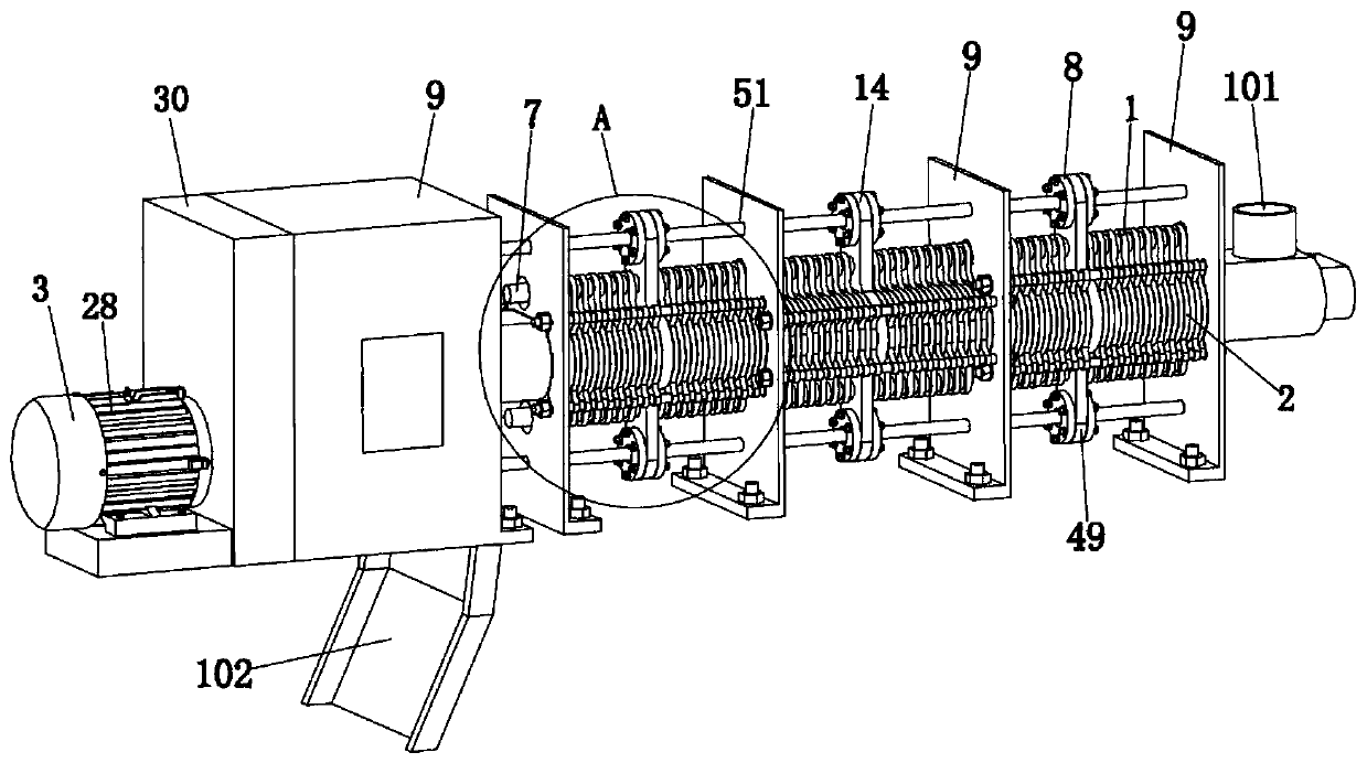
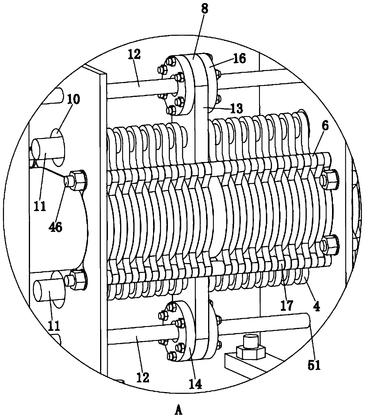
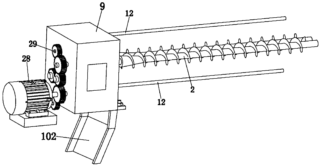
[0046] Embodiment 1: This embodiment relates to a reciprocating lamination spiral solid-liquid separator, such as Figure 1-5 As shown, it includes: a support frame 9 ; a filter cavity 1 assembled with the support frame 9 ; a screw shaft 2 mounted on the support frame 9 and penetrating through the filter cavity 1 , and a driving device 3 mounted on the support frame 9 . And the two ends of the filter cavity 1 are provided with a feed port 101 and a discharge channel 102 . Preferably, two screw shafts 2 are arranged in parallel, and the direction of rotation of the screw shafts 2 is opposite. The screw shafts 2 are used to jointly push the materials and scrape off the materials stuck on the screw shafts 2 while pushing the materials to ensure that the materials are pushed smoothness.
[0047] Such as Figure 1-5 As shown, the filter cavity 2 includes: a first closed movable ring group 4 and a second closed ring group that is inconsistent with its motion state. The two sets o...
Embodiment 2
[0066] Embodiment 2: Based on Example 1, this embodiment provides a mixing tank with a pre-concentration function, including a mixing tank and a stirring device with a pre-concentration function; the mixing tank is provided with a stirring device with a pre-concentration function; The stirring device with concentration function includes: drive device 3; as above-mentioned filter cavity 1, stirring blade, and filtrate diversion cavity 36; drive device includes drive motor 37, central shaft 38 and gear set 39 assembled with central shaft 38 The filtrate diversion cavity 36 is located at the bottom of the filter cavity 1; the filtrate diversion cavity 36 is connected with the inside of the filter cavity 1;
[0067] It should be noted that the working process of the mixing tank with pre-concentration function: in the mixing tank with pre-concentration device, the flocculated material is set in the filter cavity on the upper part of the mixing tank, and the filter cavity is due to t...
PUM
 Abstract
Description
Claims
Application Information
 - R&D Engineer
- R&D Manager
- IP Professional
- Industry Leading Data Capabilities
- Powerful AI technology
- Patent DNA Extraction
Browse by: Latest US Patents, China's latest patents, Technical Efficacy Thesaurus, Application Domain, Technology Topic, Popular Technical Reports.
© 2024 PatSnap. All rights reserved.Legal|Privacy policy|Modern Slavery Act Transparency Statement|Sitemap|About US| Contact US: help@patsnap.com


