Numerically controlled welding method with automatic compensation and filling of clearance

A technology of automatic compensation and welding method, applied in welding equipment, arc welding equipment, manufacturing tools, etc., can solve problems affecting product quality and production efficiency, welding penetration or insufficient filling, sudden shutdown of equipment, etc., to avoid the risk of equipment shutdown , reduce welding defects, reduce the effect of safety hazards

Active Publication Date: 2019-12-17
成都长客新筑轨道交通装备有限公司
View PDF9 Cites 3 Cited by
  • Summary
  • Abstract
  • Description
  • Claims
  • Application Information

AI Technical Summary

Problems solved by technology

[0003] 1. The welding parameters are fixed values. If the gap changes greatly during the welding process, manual on-site operation is required to adjust the welding parameters, which is difficult to adjust in time;
[0004] 2. Large gap fluctuations are likely to cause welding defects such as welding deviation, welding penetration or insufficient filling, which will affect product quality and production efficiency;
[0005] 3. There is a risk of equipment suddenly shutting down during the welding process, and there are potential safety hazards

Method used


Image

  • Numerically controlled welding method with automatic compensation and filling of clearance
  • Numerically controlled welding method with automatic compensation and filling of clearance
  • Numerically controlled welding method with automatic compensation and filling of clearance

Examples


Embodiment 1

[0040] A numerical control welding method for automatic gap compensation and filling provided by a preferred embodiment of the present invention includes the following steps:

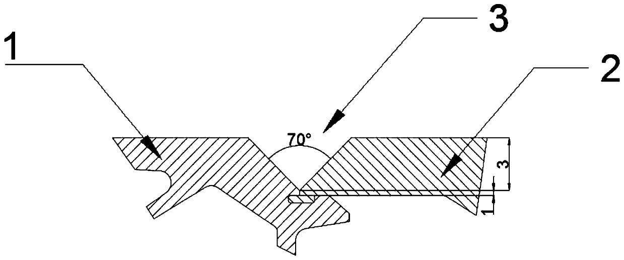
[0041] According to the groove form of the CNC welded parts, combined with the dimensional tolerance of the corresponding parts and the welding standard requirements, calculate the upper and lower extreme differences of the groove gap after assembly and obtain the fluctuation range ΔW of the groove gap value, so as to determine the upper part of the weld Spacing W, the formula for calculating the spacing W of the upper part of the weld is as follows:

[0042] W=W 1 +ΔW

[0043] Among them, W represents the distance between the upper part of the weld, and W 1 Indicates the plate thickness of the workpiece to be welded, ΔW indicates the fluctuation range of the groove gap value; W 1 It is a fixed plate thickness, a fixed value in the case of no gap. The distance W at the upper part of the weld used in...


PUM

PropertyMeasurementUnit
angleaaaaaaaaaa

Abstract

The invention discloses a numerically controlled welding method with automatic compensation and filling of clearance and relates to the technical field of numerically controlled welding. The numerically controlled welding method with automatic compensation and filling of clearance comprises the following steps that according to the groove form of a numerically controlled welded component, the fluctuation range delta W of the groove clearance numerical value is acquired through calculation, and the welding joint upper portion spacing W is determined; with the fluctuation range delta W of the groove clearance numerical value combined, the welding speed v1, the wire feeding speed v2, the swinging frequency f, and the functional relationship between arc length correction u and the welding joint upper portion spacing W are reached; and in the welding programming process, the relationship functional expression between the welding joint upper portion spacing W and each parameter is inserted,the welding joint upper portion spacing W is tracked in real time and fed back to the welding procedure, and automatic adjustment in the welding process is conducted. According to the numerically controlled welding method with automatic compensation and filling of clearance, different from a traditional circumstance that the fluctuation range delta W of the groove clearance numerical value is defined as a fixed value, when the welding joint upper portion spacing W is calculated, the fluctuation range delta W of the groove clearance numerical value is introduced; besides, the functional relationship expression between the welding joint upper portion spacing W and each parameter is inserted in welding programming; no manual operation is needed; and the method is simple, convenient and high in security.

Description

technical field [0001] The invention relates to the technical field of numerical control welding, in particular to a numerical control welding method for gap automatic compensation and filling. Background technique [0002] Numerical control welding technology has been widely used in the manufacturing process of urban rail subways and high-speed EMU car bodies. In the traditional numerical control programming welding process, the fixed welding is usually determined based on the standard groove template and the actual product groove size. parameters, so as to realize the CNC welding of the product. Although CNC welding has improved welding efficiency compared with traditional manual welding and has achieved automation to a certain extent, there are still the following problems: [0003] 1. The welding parameters are fixed values. If the gap changes greatly during the welding process, manual on-site operation is required to adjust the welding parameters, which is difficult to...

Claims


Application Information

Patent Timeline
Patent Type & Authority Applications(China)
IPC IPC(8): B23K9/095B23K9/12B23K9/127
CPCB23K9/0953B23K9/125B23K9/1274
Inventor 杨艳群姜中辉邹光厚赵冬王建王川
Owner 成都长客新筑轨道交通装备有限公司
Why Eureka
Try Eureka