Milling machine for shaft lever of camshaft of general machinery
A general-purpose machine and camshaft technology, used in milling machine equipment, details of milling machine equipment, metal processing machinery parts, etc., can solve the problems of many times of retracting the tool, high structural wear, and operator error, so as to reduce worker errors and improve finished products. High-quality, high-precision effects
- Summary
- Abstract
- Description
- Claims
- Application Information
AI Technical Summary
Problems solved by technology
Method used
Image
Examples
Embodiment 1
[0036] Embodiment 1 is basically as follows:
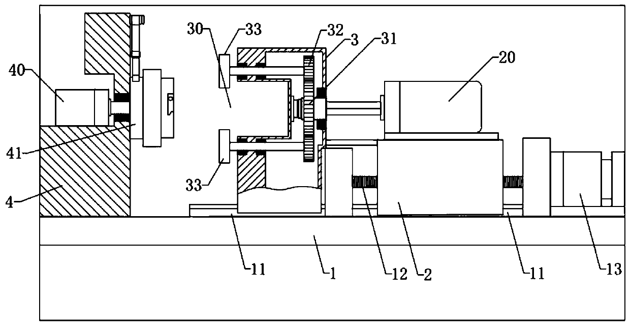
[0037] General purpose mechanical camshaft shaft milling machines such as figure 1 As shown, it includes machine 1, on which slide seat 2 is slidably connected through a translation mechanism, and the lower surface of slide seat 2 is provided with a dovetail-shaped groove; the translation mechanism includes a guide rail welded on machine table 1 and matched with the groove 11. It also includes a screw rod 12 that is rotationally connected with the machine platform 1 and arranged horizontally. The right end of the screw rod 12 is connected with a translation motor 13, and the screw rod 12 is screwed with the sliding seat 2 through a threaded through hole. When the translation motor 13 starts, it drives the screw mandrel 12 to rotate, so that the slide seat 2 moves left and right.
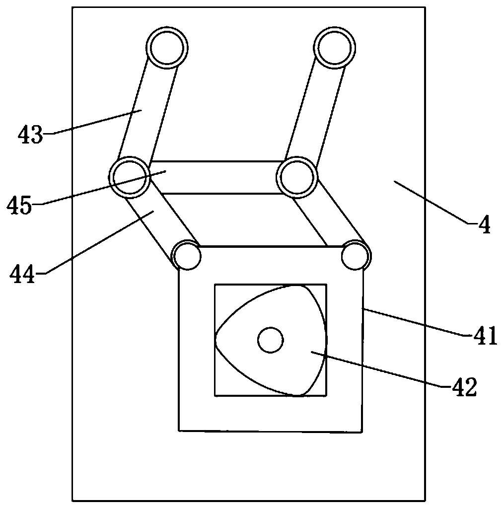
[0038] The main motor 20 is fixed on the slide 2 by screws, and the left end of the main motor 20 is connected with a tool assembly. The tool assembly...
Embodiment 2
[0045] The difference from Embodiment 1 is that, as Image 6 As shown, the clamping seat 51 is rotatably connected with the workpiece seat 50, and the workpiece seat 50 is internally provided with a rotating motor 58. The output shaft of the rotating motor 58 is connected to the workpiece seat 50 by bolts. When the rotating motor 58 is started, the clamping seat 51 is relatively The seat 50 is rotated. When the center of the clamping seat 51 reaches the apex position along the square motion track, the rotating motor 58 can be controlled to drive the clamping seat 51 to rotate an integer multiple of 90 degrees, so that the four camshafts 8 shaft rods 80 can be exchanged, so that the square The processing difference of the surface 82 is reduced, and at the same time, under the present embodiment, the number of the milling cutters 33 is reduced, and the four camshafts 8 shaft rods 80 can still be processed into a square shape.
Embodiment 3
[0047] The difference from Embodiment 1 and Embodiment 2 is that, if Figure 7 As shown, the rotating shaft between the auxiliary gear 32 and the shaft is equally divided into two sections, and the opposite ends of the two sections of the rotating shaft are fixed with a spline shaft, and the spline shaft is slidably connected with a spline sleeve 7, and the left end of the spline sleeve 7 is connected to the seat body 3 is provided with extension spring 71, and extension spring 71 two sections are all fixed with spline cover 7 and seat body 3. The corresponding processing part 30 position below the spline sleeve 7 is provided with a push block, the push block is slidably connected with the seat body 3, the upper end of the push block is offset by a wedge-shaped surface with a slide block 73, and the slide block 73 is offset against the left end of the spline sleeve 7 and is connected to the spline sleeve 7. The seat body 3 is slidingly connected. Such as Figure 8 As shown, ...
PUM
 Abstract
Description
Claims
Application Information
 - R&D
- Intellectual Property
- Life Sciences
- Materials
- Tech Scout
- Unparalleled Data Quality
- Higher Quality Content
- 60% Fewer Hallucinations
Browse by: Latest US Patents, China's latest patents, Technical Efficacy Thesaurus, Application Domain, Technology Topic, Popular Technical Reports.
© 2025 PatSnap. All rights reserved.Legal|Privacy policy|Modern Slavery Act Transparency Statement|Sitemap|About US| Contact US: help@patsnap.com


