
Design method of bi-planar shimming coil

A technology of shim coils and design methods, applied in calculation, special data processing applications, measurement devices, etc., can solve problems such as poor imaging quality, inability to image, and inhomogeneity of the main magnetic field of an open MRI magnet, and achieve improved uniformity. performance and image quality, and the effect of eliminating harmonic magnetic fields

Inactive Publication Date: 2019-12-13
HUIREN WANGDU MEDICAL EQUIP SCI & TECH CO LTD
View PDF6 Cites 11 Cited by
  • Summary
  • Abstract
  • Description
  • Claims
  • Application Information

AI Technical Summary

Problems solved by technology

[0002] Magnetic resonance imaging (Manetic Resonance ImagingMRI) technology is a technology that crosses multiple technologies, including electromagnetics, digital signal processing, biomedicine and atomic physics. Compared with other medical imaging technologies, MRI has the advantages of no radiation and high resolution. and clear image quality, so MRI technology has important clinical application value in medical examination. Ideally, the main magnetic field of MRI equipment is only B0 field, and there are no other harmonic magnetic fields. Avoid the introduction of harmonic magnetic fields that are not B0 fields. The introduction of harmonic magnetic fields will make imaging quality worse or even impossible. Gradient coils can correct the first-order harmonic magnetic field, and the magnetic field higher than the first-order harmonic requires second-order and above The shimming coil is used to eliminate it, so that the B0 field reaches the range required by the imaging
[0003] In order to solve the above-mentioned problem of inhomogeneity of the main magnetic field of the open MRI magnet, the patent of the present invention proposes a design method of a double-plane shim coil

Method used


Image

  • Design method of bi-planar shimming coil
  • Design method of bi-planar shimming coil
  • Design method of bi-planar shimming coil

Examples


Embodiment Construction

[0023] Embodiments of the present invention will be further described below in conjunction with the accompanying drawings.

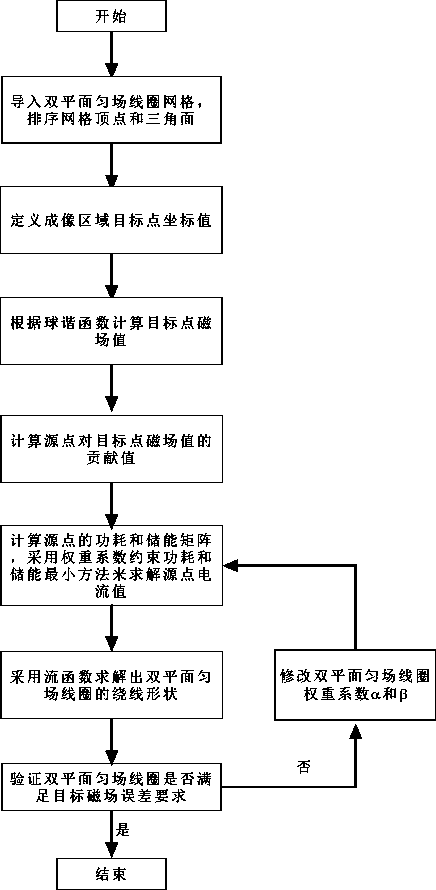
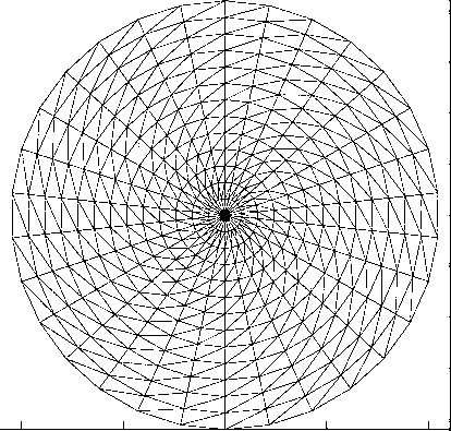
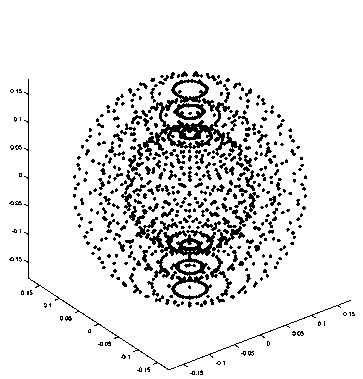
[0024] The present invention introduces the design method of a double-plane shim coil of the present invention by taking 3 groups of 2-order axial shim coils: Z20, Z21, and Z22 as design examples. The design flow chart is as follows figure 1 As shown, the design parameters of the double-plane shim coils are set. The diameter of the double-plane shim coils is a triangular mesh of 0.42m, and the spacing is 500mm. Each sphere is divided into 16 layers on spheres with diameters of 100mm, 240mm and 360mm. Set a test point every 11.6°, a total of 1488 target points, the error is not greater than 5%, the specific design steps are as follows.

[0025] Step 1: According to the design parameters of the set biplane shim coils, the blender2.8 software is used to divide the shim coils into triangular meshes, that is, to discretize the shim coils into nodes and triang...


PUM


Abstract

The invention discloses a design method of a bi-planar shimming coil. According to the design method, the source point grid of a biplanar shimming coil is imported; grid vertexes and triangular surfaces are sequenced; the magnetic field values of a second-order shimming coil on target points are calculated through a spherical harmonic function; MATLAB software is adopted to read each vertex and each surface of the triangular grids; the arrangement sequence of the vertexes and surfaces is optimized; the size of a wire is set according to a boundary element method; the value of the contributionof an electrified wire in a source point region to field points is calculated; the energy storage and power consumption of the bi-planar shimming coil are constrained to be minimum; current density distribution on the biplanar shimming coil is solved; and the winding shape of the bi-planar shimming coil is obtained through a stream function method. With the design method of the bi-planar shimmingcoil adopted, harmonic magnetic fields of a second order or higher orders can be eliminated, so that the uniformity of a main magnetic field is improved, and the image quality of an open type MRI system is improved.

Description

technical field [0001] The invention relates to the field of magnetic resonance imaging, in particular to a design method of a double-plane shim coil. Background technique [0002] Magnetic resonance imaging (Manetic Resonance ImagingMRI) technology is a technology that crosses multiple technologies, including electromagnetics, digital signal processing, biomedicine and atomic physics. Compared with other medical imaging technologies, MRI has no radiation and high resolution. and clear image quality, so MRI technology has important clinical application value in medical examination. Ideally, the main magnetic field of MRI equipment is only B0 field, and there are no other harmonic magnetic fields. Avoid the introduction of harmonic magnetic fields that are not B0 fields. The introduction of harmonic magnetic fields will make imaging quality worse or even impossible. Gradient coils can correct the first-order harmonic magnetic field, and the magnetic field higher than the firs...

Claims


Application Information

Patent Timeline
Patent Type & Authority Applications(China)
IPC IPC(8): G01R33/387G06F17/50
CPCG01R33/387
Inventor 李良安侯荣芹陈琳鑫安学亮
Owner HUIREN WANGDU MEDICAL EQUIP SCI & TECH CO LTD
Learn More