Pushing device for copper ore sampling
A pusher device and copper ore technology, applied in the field of pusher device, can solve the problems of inconvenient operation, troublesome operation, and high requirements on the length of the telescopic rod of the cylinder, and achieve the effects of portability, simple structure, and low production cost
- Summary
- Abstract
- Description
- Claims
- Application Information
AI Technical Summary
Problems solved by technology
Method used
Image

Examples
Embodiment 1
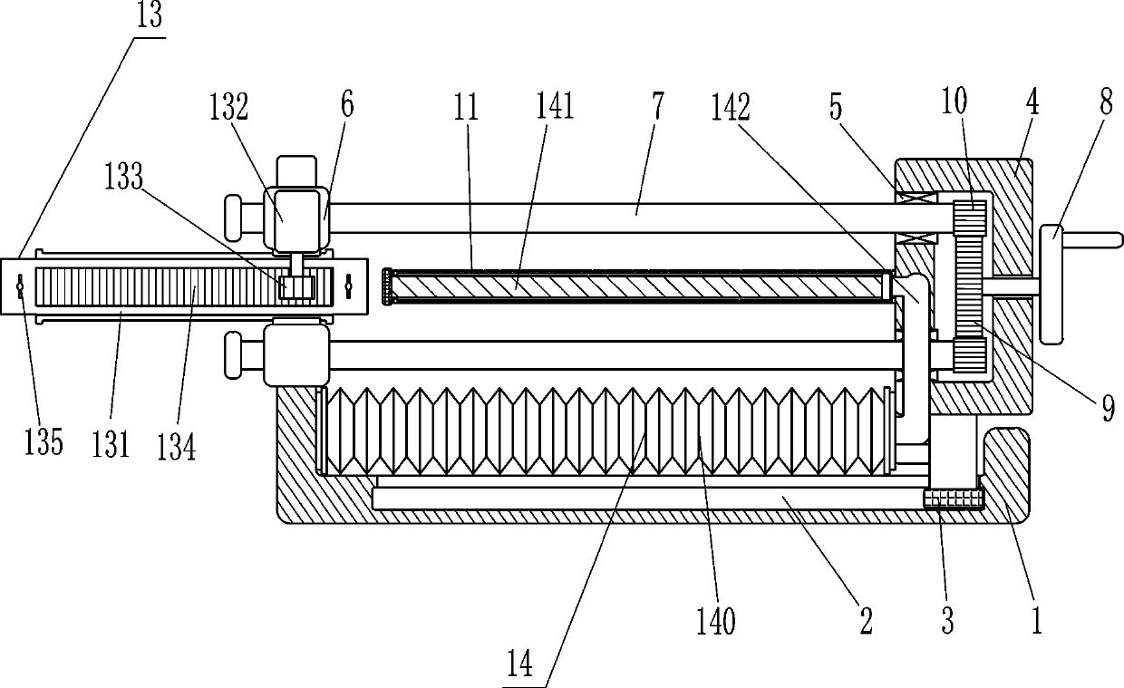
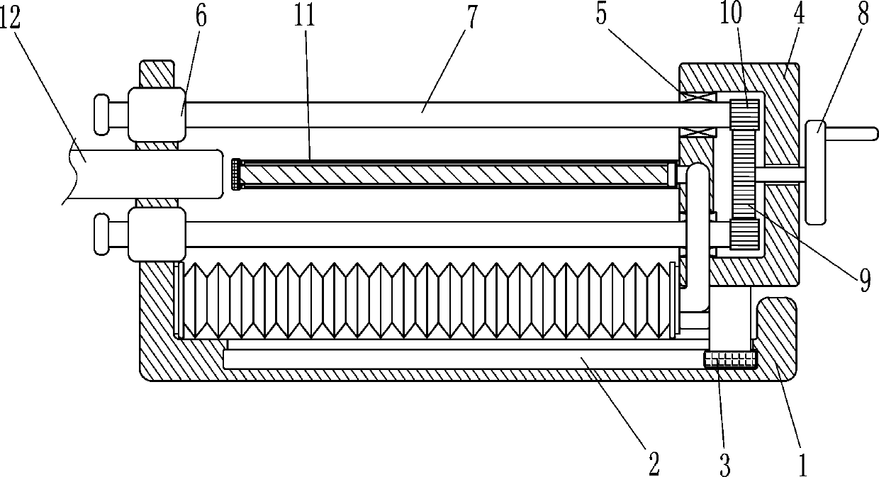
[0017] Such as figure 1 with image 3 As shown, a pushing device for copper ore sampling includes a mounting base 1, a slider 3 and a rectangular housing 4, the inner bottom of the mounting base 1 is provided with a guide groove 2, and the guide groove 2 is slidingly provided with The slider 3, the top of the slider 3 is connected with a rectangular housing 4, the slider 3 and the rectangular housing 4 are connected by bolts, and also includes a bearing seat 5, a threaded sleeve 6, a threaded rod 7 and a feeding mechanism. The upper and lower parts of the housing 4 are embedded with bearing seats 5, the two bearing seats 5 are symmetrical up and down, and the upper and lower sides of the left part of the mounting seat 1 are equipped with threaded sleeves 6, and the axes of the two threaded sleeves 6 are aligned with the two The axes of the two bearing seats 5 are located on the same horizontal line, the internal thread of the threaded sleeve 6 is matched with a threaded rod 7...
Embodiment 2
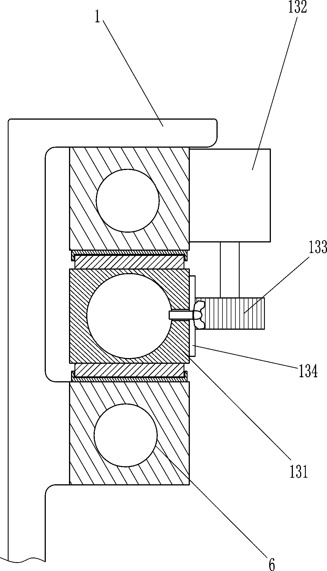
[0020] Such as figure 2 with image 3 As shown, also includes moving device 13, and moving device 13 includes hollow pipe 131, motor 132, the 3rd gear 133, tooth bar 134 and fixed bolt 135, is provided with for placing coring between the upper and lower two threaded sleeves 6. The hollow tube 131 of the casing 12, the hollow tube 131 is located on the right left of the outer push rod 11, the front side of the hollow tube 131 is provided with a rack 134, the rack 134 is connected with the hollow tube 131 by means of bolt connection, and the upper threaded sleeve 6. A motor 132 is provided on the front side, and a third gear 133 is connected to the output shaft of the motor 132. The third gear 133 meshes with the rack 134. The hollow tube 131 is provided with a fixing bolt 135 for fixing the coring sleeve 12.
[0021] When it is necessary to take out the rock sample, put the coring casing 12 equipped with the rock sample into the hollow pipe 131, tighten the fixing bolt 135 to...
Embodiment 3
[0023] Such as figure 1 Shown, also comprise booster device 14, booster device 14 comprises telescoping airbag 140, inner push rod 141 and air pipe 142, and the inner push rod 141 of outer push rod 11 sliding type is provided with, and mounting seat 1 inner wall and rectangular A telescopic airbag 140 is connected between the housings 4, and the telescopic airbag 140 is parallel to the mounting base 1. A ventilation pipe 142 is connected to the telescopic airbag 140. The tail end of the ventilation pipe 142 is connected to the head end of the outer push rod 11, and the outer push rod 11 passes through the The ventilation tube 142 communicates with the inside of the telescopic air bag 140 .
[0024] When the outer push rod 11 is pushing the rock sample, the rectangular housing 4 drives the telescopic air bag 140 to compress, and the gas in the telescopic air bag 140 pushes the inner push rod 141 toward the coring sleeve 12 through the vent tube 142, thereby the coring The rock...
PUM
 Abstract
Description
Claims
Application Information
 - R&D
- Intellectual Property
- Life Sciences
- Materials
- Tech Scout
- Unparalleled Data Quality
- Higher Quality Content
- 60% Fewer Hallucinations
Browse by: Latest US Patents, China's latest patents, Technical Efficacy Thesaurus, Application Domain, Technology Topic, Popular Technical Reports.
© 2025 PatSnap. All rights reserved.Legal|Privacy policy|Modern Slavery Act Transparency Statement|Sitemap|About US| Contact US: help@patsnap.com