Eureka AIR delivers breakthrough ideas for toughest innovation challenges, trusted by R&D personnel around the world.

Three-phase heat exchanger and absorption type refrigeration system comprising same

An absorption refrigeration and heat exchanger technology, applied in the direction of heat exchanger shell, indirect heat exchanger, heat exchanger type, etc., can solve the problems of unsuitable absorption refrigeration system, difficult processing, complicated design, etc. Improve energy utilization efficiency, compact structure, and reduce the effect of heat source heat

Active Publication Date: 2019-12-13
ANHUI WATERPOWER ENERGY SAVING TECH
View PDF8 Cites 4 Cited by
  • Summary
  • Abstract
  • Description
  • Claims
  • Application Information

AI Technical Summary

Problems solved by technology

[0005] 1. The temperature of the rich solution after heat exchange through the intermediate heat exchanger is still lower than the temperature in the generator, and a large amount of heating is still required after reaching the generator
[0006] 2. The ammonia gas from the generator needs to be cooled by the condenser, and the cooling capacity is relatively large
[0007] In order to solve the contradiction that the above-mentioned rich solution needs to be heated and ammonia needs to be cooled, a three-phase heat exchanger can be used to replace the intermediate heat exchanger of the original process, but the conventional three-phase heat exchanger is mostly a coiled heat exchanger, which is difficult to process Large, complex design, not suitable for application in absorption refrigeration systems

Method used


Image

  • Three-phase heat exchanger and absorption type refrigeration system comprising same
  • Three-phase heat exchanger and absorption type refrigeration system comprising same
  • Three-phase heat exchanger and absorption type refrigeration system comprising same

Examples


Embodiment 1

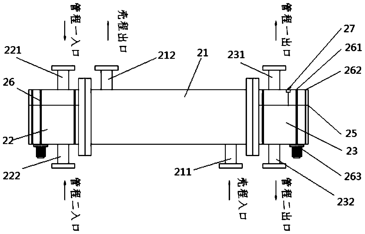
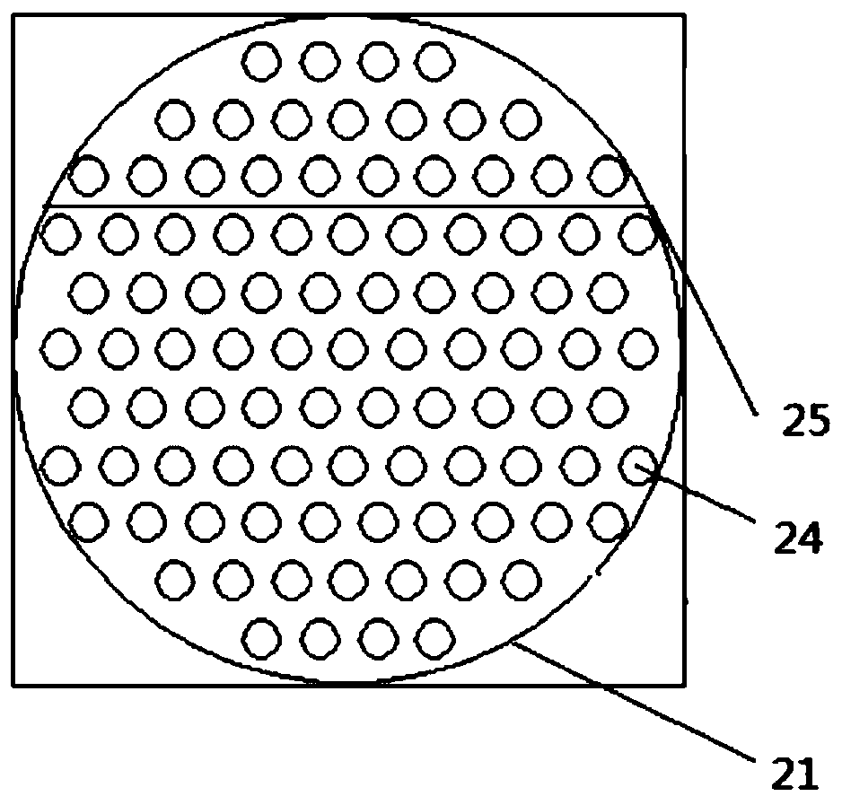
[0028] This embodiment provides a three-phase heat exchanger 2, such as Figure 2-3 As shown, the shell-side cylinder 21 is included, the shell-side cylinder 21 is provided with a plurality of shell-and-tube heat exchange tubes 24, and the two ends of the shell-side cylinder 21 are respectively provided with a first tube-side cylinder 22 and the second tube-side cylinder 23, the first tube-side cylinder 22 and the second tube-side cylinder 23 communicate through the heat exchange tube 24, and the shell-side cylinder 21 is provided with a shell-side inlet 211, a shell-side The outlet 212, the shell-side inlets and outlets 211, 212 communicate with the heat exchange tube 24 to form a shell-side passage, and the first tube-side cylinder 22 is provided with two tube-side inlets, which are respectively the first tube-side inlet 221 and the second tube-side inlet Inlet 222, the second tube pass cylinder 23 is provided with two tube pass outlets, which are respectively the first tube...


PUM


Abstract

The invention relates to a three-phase heat exchanger and an absorption refrigeration system comprising the same, and belongs to the technical field of refrigeration systems. The three-phase heat exchanger comprises a shell pass barrel body and two tube pass barrel bodies, wherein the two tube pass barrel bodies communicate with each other through heat exchange tubes; a shell pass inlet and a shell pass outlet are formed in the shell pass barrel body; two tube pass inlets are formed in one tube pass barrel body and two tube pass outlets are formed in the other tube pass barrel body; and a tubepass partition plate is arranged between the tube pass inlets of one tube pass barrel body, the other tube pass partition plate is arranged between the tube pass outlets of the other tube pass barrelbody, and each heat exchange tube is divided into two tube pass channels which are independent from each other through the tube pass partition plates. Compared with an existing absorption type refrigeration system utilizing two common heat exchangers, the three-phase heat exchanger and the absorption type refrigeration system comprising the same are more compact in structure, and the occupied area and space are saved; and a column tube type heat exchanger is adopted and the manufacturing is simple. The distribution ratio between the two tube passes is realized through the different positionsof the tube pass partition plates, the design and calculation are simple, and thus the heat exchange efficiency is higher. Through the design of the inlets and outlets, the heat exchange process is fully countercurrent, and thus the heat exchange efficiency is higher.

Description

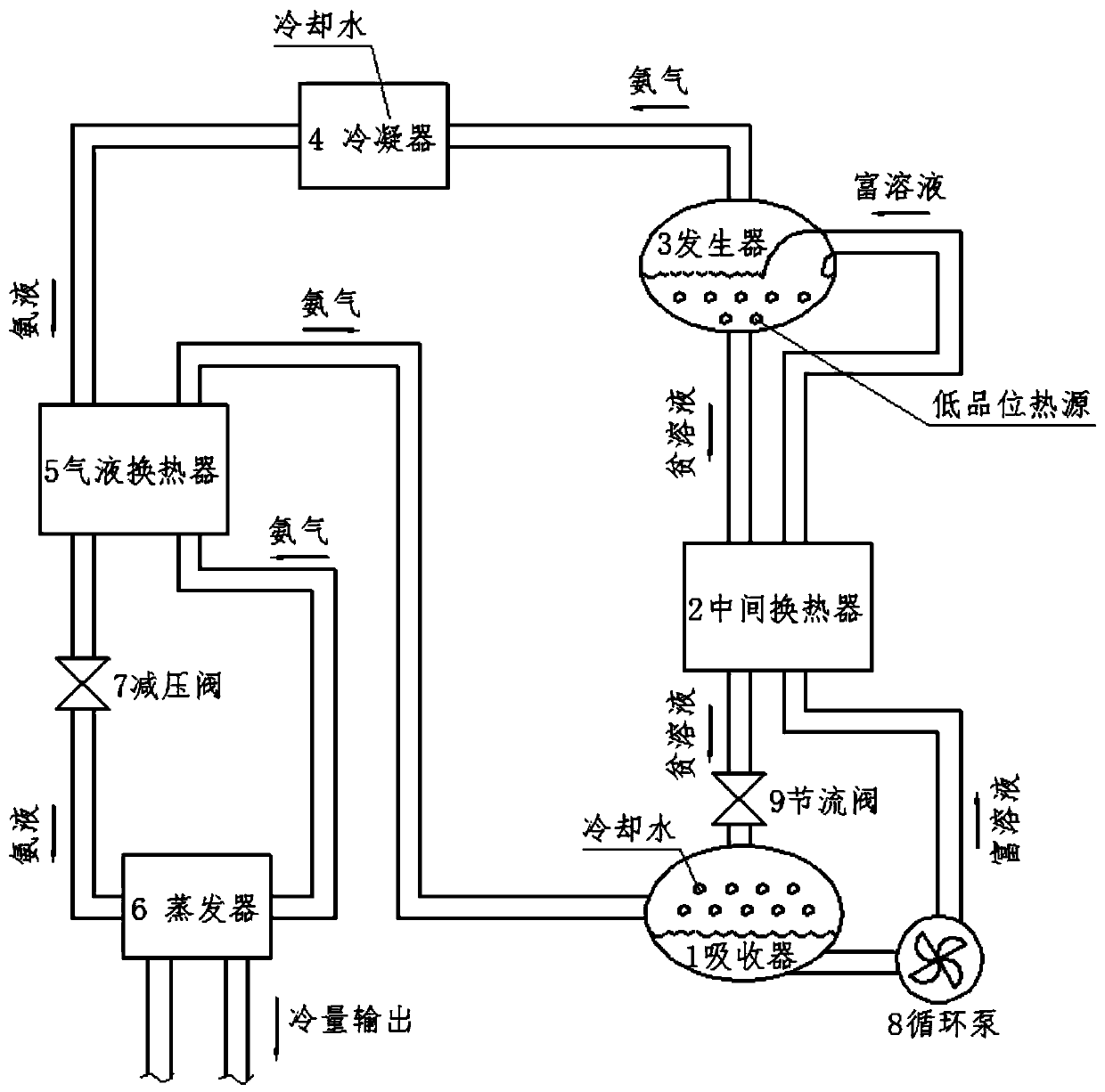
technical field [0001] The invention relates to the technical field of refrigeration systems, in particular to a three-phase heat exchanger and an absorption refrigeration system thereof. Background technique [0002] The absorption refrigeration unit is mainly composed of generators, absorbers, evaporators and other heat exchangers, pumps, valves, etc., and realizes refrigeration through the phase change of the working fluid (such as ammonia). [0003] Currently common absorption refrigeration units, such as figure 1 As shown, it includes an absorber, an intermediate heat exchanger, a generator, a condenser, a gas-liquid heat exchanger, and an evaporator, and the rich solution output of the absorber is connected to the rich solution input of the generator through a rich solution pipeline , the lean solution output end of the generator is connected with the lean solution input end of the absorber through the lean solution pipeline, and the ammonia gas output end of the gene...

Claims


Application Information

Patent Timeline
Patent Type & Authority Applications(China)
IPC IPC(8): F28D7/16F28F9/00F25B15/04
CPCF25B15/04F28D7/16F28F9/005Y02B30/62Y02A30/27
Inventor 祝令辉方磊陈何根姚传辉徐超崔浩
Owner ANHUI WATERPOWER ENERGY SAVING TECH
Why Eureka
Eureka Blog
Learn More