
Method for distinguishing coal spontaneous combustiondangerous zone by using goaf air leakage

A technology for dangerous areas and goafs, applied in mining equipment, mining equipment, earthwork drilling, etc., can solve the problems of wasting resources, increasing the blindness of fire area control, reducing the number of installations, improving the effect of air leakage detection, and facilitating The effect of promotion

Active Publication Date: 2019-12-13
XIAN UNIV OF SCI & TECH
View PDF12 Cites 9 Cited by
  • Summary
  • Abstract
  • Description
  • Claims
  • Application Information

AI Technical Summary

Problems solved by technology

The spontaneous combustion area of ​​the goaf has great ambiguity in determining the location of the fire source, which increases the blindness of fire area governance, expands the governance area, and wastes resources
[0003] According to the coal-oxygen composite theory of coal spontaneous combustion and actual production experience, coal spontaneous combustion must meet four conditions: first, the coal with natural tendency is in a broken state after mining, and the accumulation thickness is generally greater than 0.4m; second, it has good storage capacity. The third is continuous oxygen supply; the fourth is long enough time; therefore, in the process of coal mining, the concentration of oxygen in the goaf must be controlled while improving the recovery rate as much as possible to reduce the coal left in the goaf , air leakage in the goaf is the biggest threat to oxygen rise in the goaf, but the existing technology lacks high-efficiency, high-precision, and high-dimensional measurement and identification of air leakage in the gob

Method used


Image

  • Method for distinguishing coal spontaneous combustiondangerous zone by using goaf air leakage
  • Method for distinguishing coal spontaneous combustiondangerous zone by using goaf air leakage
  • Method for distinguishing coal spontaneous combustiondangerous zone by using goaf air leakage

Examples


Embodiment Construction

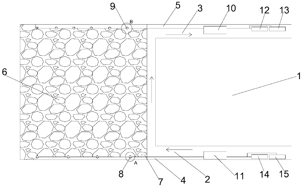
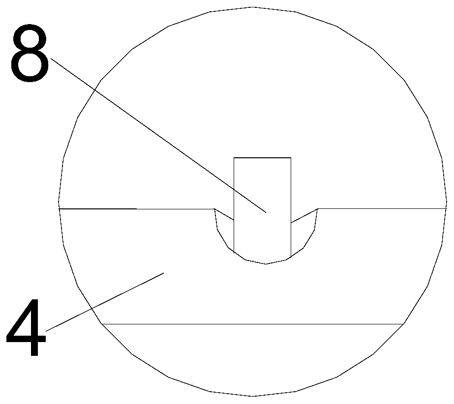
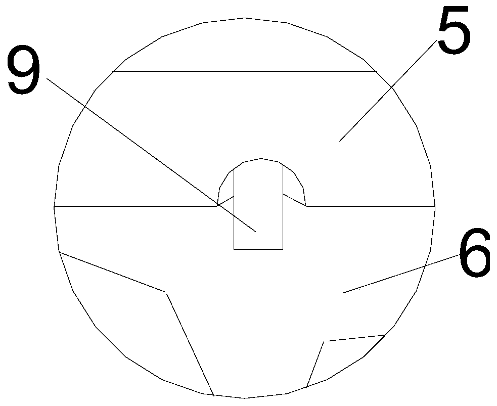
[0045] Such as Figures 1 to 5 As shown in the present invention, a method for discriminating coal spontaneous combustion dangerous areas by using goaf air leakage according to the present invention utilizes gob air leakage devices to monitor coal spontaneous combustion dangerous areas. The air inlet side sampling protection pipe 4 arranged near the side of the coal bank and the air return side sampling protection pipe 5 arranged along the side of the return air side trough 3 close to the coal side, the air inlet side sampling protection pipe 4 is far away from the air inlet side On the pipe section along the outlet of slot 2 and along its length direction, M monitoring ports 8 on the air inlet side are arranged, and on the pipe section along the outlet of slot 3 on the return air side, N monitoring ports are arranged along its length direction. The monitoring port 9 on the air return side, wherein M and N are both positive integers and M is less than N; the sampling protectio...


PUM


Abstract

The invention discloses a method for distinguishing a coal spontaneous combustion dangerous zone by using goaf air leakage. The method includes the steps that 1, a monitoring opening is formed; 2, oxygen distribution in a goaf is monitored; 3, the step 2 is repeated for several times until the advance distance of the coal face reaches the specified advance distance; 4, SF6 tracer gas release device is mounted; 5, SF6 tracer gas and the oxygen distribution in the goaf are monitored; and 6, the air leakage speed is determined. According to the method, M air inlet side monitoring openings and theSF6 tracer gas release device are arranged on an air inlet side sampling protection pipe in an air inlet side gate road, N air return side monitoring opening are formed in an air return side samplingprotection pipe in an air return side gate road, the oxygen distribution in the goaf is monitored by using a gas chromatograph, a SF6 tracer gas determinator is used for determining distribution of the SF6 tracer gas, the air leakage condition in the goaf is monitored by double-gas, and then the coal spontaneous combustion dangerous zone is distinguished, and the degree of accuracy is high.

Description

technical field [0001] The invention belongs to the technical field of air leakage monitoring in goafs, and in particular relates to a method for discriminating coal spontaneous combustion dangerous areas by using air leakage in goafs. Background technique [0002] Spontaneous coal seam fires in mines have become one of the major disasters that directly threaten the safe production of mines. According to statistics, about 80% of the coal seams that have been mined in my country have the tendency of coal spontaneous combustion; especially in recent years, the vigorous promotion of fully mechanized top-coal caving mining technology in my country has greatly improved coal production efficiency and coal output. A large amount of floating coal is left in the goaf, which causes coal spontaneous combustion fires to occur frequently in more and more mines, especially in high-gas mines. The air leakage in the area is very serious. In the case of sufficient oxygen, the residual coal is...

Claims


Application Information

Patent Timeline
IPC IPC(8): E21F17/00G01N1/22G01N30/02G01T1/167
CPCE21F17/00G01N1/2247G01N30/02G01T1/167
Inventor 马砺崔鑫峰郭睿智易欣薛梦华于文聪刘尚明
Owner XIAN UNIV OF SCI & TECH
Learn More