
Airtight tank type decoking dehydration tank

A closed tank, dehydration tank technology, applied in the direction of fixed filter element filter, gravity filter, lighting and heating equipment, etc., can solve the problems of atmospheric environment pollution, lack of efficient and environmentally friendly dehydration petroleum coke dehydration device, harmful to the body, etc. Improve the effect of filtering

Pending Publication Date: 2019-12-13
涧光(上海)特种装备有限公司
View PDF0 Cites 0 Cited by
  • Summary
  • Abstract
  • Description
  • Claims
  • Application Information

AI Technical Summary

Problems solved by technology

[0002] In the existing decoking technology, petroleum coke is transported from the coke tower to the open-air coke storage pool for storage and dehydration. The dehydration process is natural dehydration in the open air. The entire dehydration process is uncontrollable, and a large amount of waste gas and coke powder particles will be generated during the dehydration process. The atmospheric environment is seriously polluted, which is harmful to the health of the personnel working on site; after the dehydration is completed, the petroleum coke is transported by a grab crane or a screw conveyor. The entire transport process is time-consuming and laborious, and dust is easily generated on site. There is a lack of petroleum coke dehydration devices that can efficiently and environmentally friendly dehydrate petroleum coke and transport smoothly

Method used


Image

  • Airtight tank type decoking dehydration tank
  • Airtight tank type decoking dehydration tank
  • Airtight tank type decoking dehydration tank

Examples


specific Embodiment approach

[0030] Referring to the accompanying drawings, the specific implementation is as follows:

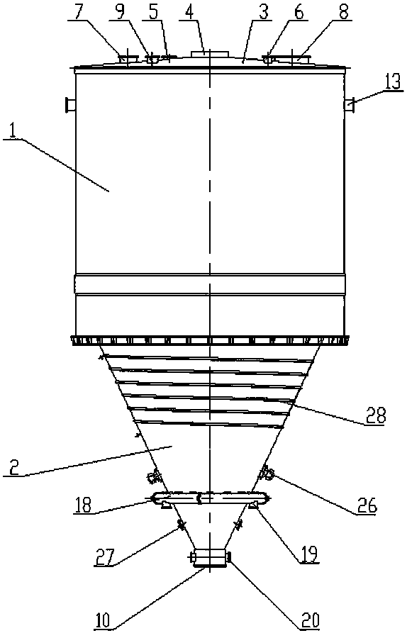
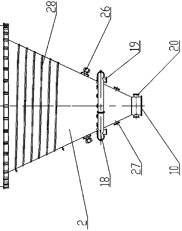
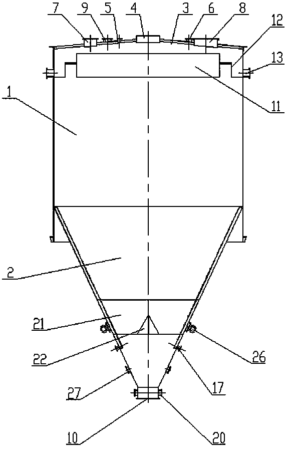
[0031] Such as Figure 1-4 As shown, a closed tank type decoking and dehydration tank includes a vertically arranged cylinder 1 and a cone 2 located below the cylinder 1, the large end of the cone 2 is connected to the bottom end of the cylinder 1, and the cylinder 1 A top cover 3 is installed on the top, and a material inlet 4 is provided on the top cover 3. A material outlet 10 is provided at the small end of the cone 2. The top cover 3 is also provided with an exhaust port 5, a water inlet 6, a manhole 7, maintenance The hole 8 and the nozzle 9 of the level gauge, the cylinder 1 is provided with an overflow assembly, the overflow assembly includes a disc-shaped foam coke baffle 11 and a zigzag overflow set on the outer circumference of the foam coke baffle 11 Weir 12, the zigzag overflow weir 12 is connected with the inner wall of the cylinder 1, and the side wall of the cylinder 1 ...


PUM


Abstract

The invention relates to an airtight tank type decoking dehydration tank, which comprises a cylinder, a top cover and a taper cylinder under the cylinder. The top cover is equipped with a material inlet, the small end of the taper cylinder is equipped with a material outlet, the cylinder is internally equipped with an overflow assembly, and overflow holes are disposed on the side wall of the cylinder; the taper cylinder is internally equipped with a plurality of water filtration assemblies, each water filtration assembly includes two long strip-shaped supports attached to the inner wall of thetaper cylinder, two sets of rib plates are cooperatively arranged on the two supports in a spaced mode, the two sets of rib plates are perpendicular to each other in the length direction, and screenholes formed by cooperation of the two sets of rib plates are utilized for water filtration, a plurality of water outlet pipes and an annular pipe are connected to the side wall of the taper cylinder,and the bottom side of the annular pipe is equipped with a plurality of water outlets; the side wall at the bottom of the taper cylinder is equipped with a plurality of bottom water filtration ports,which are located below the annular pipe and are internally equipped with a cylindrical filter plate assembly; and the taper cylinder is internally equipped with an anti-blocking device for partitioning the inner cavity of the taper cylinder so as to prevent materials from blocking the outlet. The airtight tank type decoking dehydration tank provided by the invention can achieve efficient and environment-friendly dehydration and smooth transportation of petroleum coke.

Description

technical field [0001] The invention relates to the field of petroleum coke production devices, in particular to a closed tank type decoking and dehydrating tank. Background technique [0002] In the existing decoking technology, petroleum coke is transported from the coke tower to the open-air coke storage pool for storage and dehydration. The dehydration process is natural dehydration in the open air. The entire dehydration process is uncontrollable, and a large amount of waste gas and coke powder particles will be generated during the dehydration process. The atmospheric environment is seriously polluted, which is harmful to the health of the personnel working on site; after the dehydration is completed, the petroleum coke is transported by a grab crane or a screw conveyor. The entire transport process is time-consuming and laborious, and dust is easily generated on site. There is a lack of a petroleum coke dehydration device that can efficiently and environmentally frien...

Claims


Application Information

Patent Timeline
Patent Type & Authority Applications(China)
IPC IPC(8): B01D29/31B01D29/01F26B21/00
CPCB01D29/31B01D29/014F26B21/004
Inventor 刘志平杨腾云
Owner 涧光(上海)特种装备有限公司
Learn More