
Liftable weak current box and weak current well

A technology of weak current well and weak current box, which is applied in the cable installation, electrical components, cable installation and other directions in the cable room to achieve the effect of reducing the probability of fire

Active Publication Date: 2019-12-10
成都理工智联科技有限公司
View PDF11 Cites 2 Cited by
  • Summary
  • Abstract
  • Description
  • Claims
  • Application Information

AI Technical Summary

Problems solved by technology

[0004] The purpose of the present invention is to overcome the shortcomings of the prior art that when a fire is found at the place where the weak current box is placed in the weak current well, it cannot quickly and timely deal with the fire on the basis of less impact on the outside of the weak current well, and provides a liftable weak current box and Weak electric well, by lifting and lowering the weak electric box in the weak electric well, the weak electric box can be effectively placed in different spaces, and the impact on the outside of the weak electric well can be minimized on the basis of quick and timely handling of the fire of the weak electric box

Method used


Image

  • Liftable weak current box and weak current well
  • Liftable weak current box and weak current well
  • Liftable weak current box and weak current well

Examples


Embodiment 1

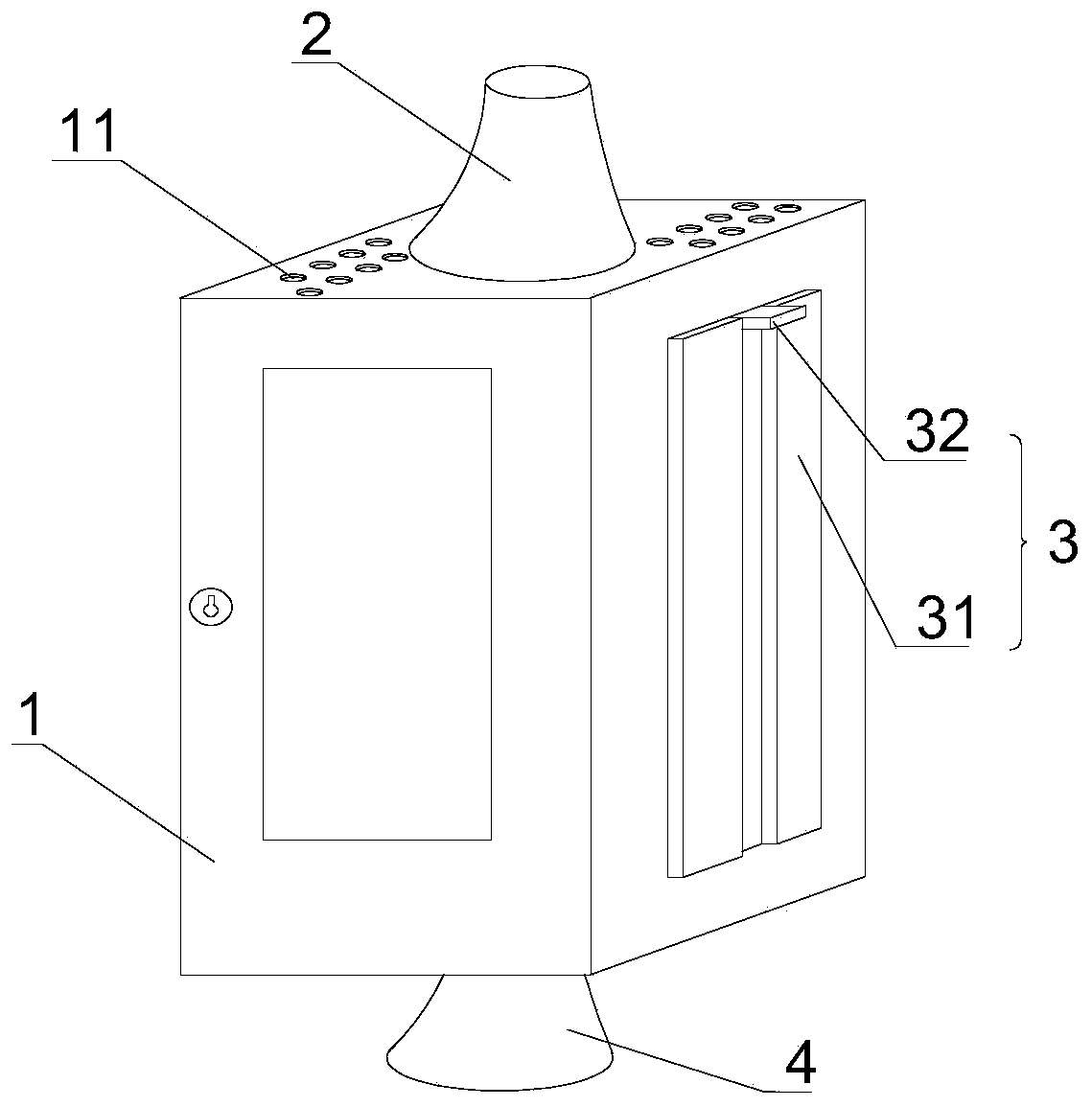
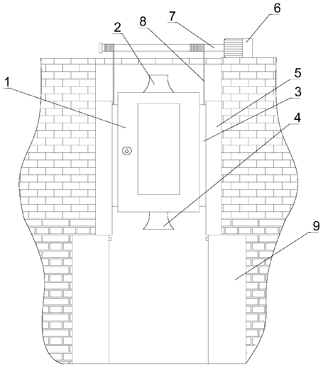
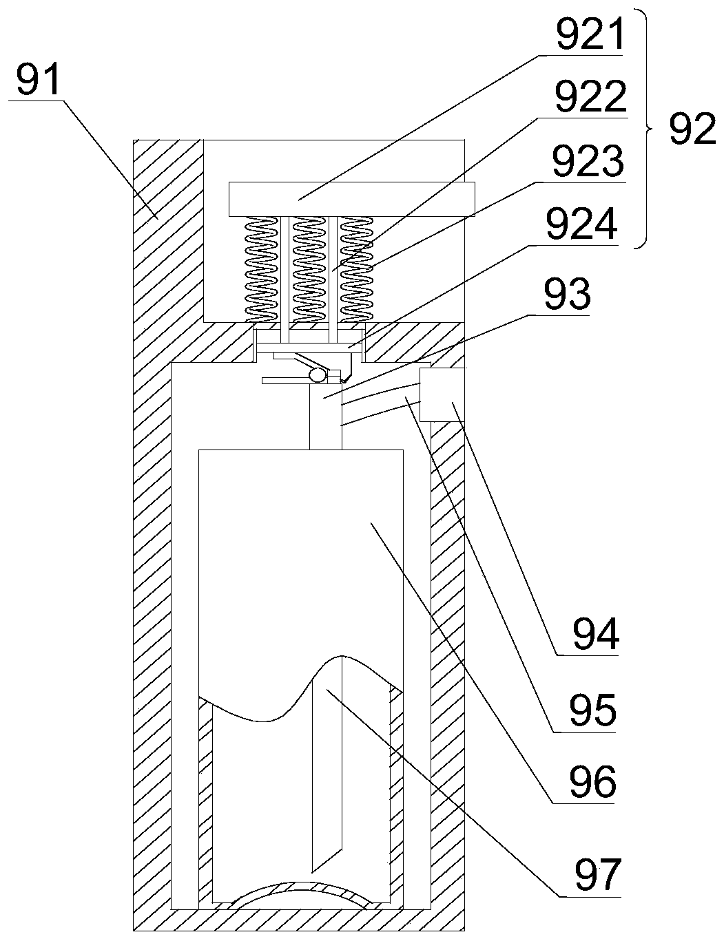
[0030] Such as Figure 1~4 As shown, a liftable weak electric box and a weak electric well include a hollow rectangular parallelepiped weak electric well and a weak electric box 1 located in the weak electric well. The weak electric box 1 has two symmetrical sides in contact with the inner wall of the weak electric well. The sides of the box body 1 in contact with the inner wall of the weak current well are provided with sliders 3 protruding from the surface of the weak current box body 1, the inner wall of the weak current well is provided with a slideway 5 corresponding to the position of the slider 3, and the bottom of the weak current well is also equipped with an opening structure The fire extinguishing device 9 at the top, the top of the fire extinguishing device 9 is in contact with the bottom end surface of the slideway 5, a rotating shaft 7 is arranged above the top wall of the weak current well, and a pressure-bearing cable 8 is arranged on the rotating shaft 7, and t...

Embodiment 2

[0036] Such as Figure 1~5 As shown, on the basis of Embodiment 1, the upper surface of the weak current box 1 is provided with an upper reducer 2, and the nozzle of the upper reducer 2 close to the weak current box 1 is large, far away from the weak current box 1 One side of the gate is small, the upper reducer 2 is fixedly connected to the upper surface of the weak current box 1 and communicates with the inside of the weak current box 1, the lower surface of the weak current box 1 is provided with a lower reducer 4, and the lower reducer 4 is close to The nozzle on the side of the weak current box 1 is small, and the nozzle on the side away from the weak current box 1 is large. The lower reducer 4 is fixedly connected to the lower surface of the weak current box 1 and communicates with the inside of the weak current box 1. The weak current box 1 The upper surface of the upper surface is also provided with some ventilation holes 11, and the ventilation holes 11 are symmetrica...


PUM


Abstract

The invention discloses a liftable weak current box and a weak current well. The weak current well and the weak current box body located in the weak current well are included. Slide blocks protrudingout of a surface of the weak current box body are arranged on side surfaces, which are in contact with an inner wall of the weak current well, of the weak current box body. Slideways corresponding topositions of the slide blocks are arranged on the inner wall of the weak current well. A rotating shaft is arranged above a top wall of the weak current well. A pressure-bearing cable is arranged on the rotating shaft, one end of the pressure-bearing cable is fixedly connected with the slide blocks, and the other end is fixedly connected with the rotating shaft and wound on the rotating shaft. Therotating shaft is driven by a motor, a fire extinguishing device capable of being opened through descending of the weak current box body is further arranged at a bottom of the weak current well. A top of the fire extinguishing device is in contact with bottom end surfaces of the slideways. The weak current box body is controlled to ascend and descend through rolling and releasing of the pressure-bearing cable, an outlet of the fire extinguishing device is opened through the weak current box body to achieve a purpose of fire extinguishing, the weak current box is effectively placed in different spaces, and on the basis that a fire behavior of the weak current box is rapidly and timely handled, an influence outside the weak current well is minimized.

Description

technical field [0001] The invention relates to the field of centralized control equipment for weak current pipelines, in particular to a liftable weak current box and a weak current well. Background technique [0002] The weak current shaft is a vertical shaft built for the convenience of laying cables for the weak current system of the building, referred to as the weak current shaft. The rapid development of building intelligence for many years has made weak current wells widely used in various buildings, and the use of weak current wells has also made the planning and design of building intelligence more standardized. The weak current lines in the weak current well include the lines of computer network, cable TV, mobile phone signal, monitoring system, etc., and these lines are concentrated in the weak current box for control. [0003] In the public area of ​​the building, when an accident occurs, the existence of monitoring and sensors can detect the accident in time, b...

Claims


Application Information

Patent Timeline
IPC IPC(8): H02B1/46H02B1/56H02G9/10A62C3/16A62C35/02A62C99/00
CPCA62C3/16A62C35/02A62C99/0027H02B1/46H02B1/565H02G9/10
Inventor 周昱希
Owner 成都理工智联科技有限公司
Learn More