
Centralized treatment control method for cutting fluids of carving centers

A control method and centralized processing technology, which can be used in engraving, decorative arts, processing models, etc., can solve the problems of large workload, high work intensity, time-consuming and laborious, etc., to achieve uniform concentration, ensure stability, and improve quality.

Active Publication Date: 2019-12-10
西安精雕软件科技有限公司
View PDF18 Cites 0 Cited by
  • Summary
  • Abstract
  • Description
  • Claims
  • Application Information

AI Technical Summary

Problems solved by technology

[0007] 1. The manual operation method is labor-intensive and time-consuming, especially when the number of equipment is large, the workload is very large;
[0008] 2. Manual operation may forget to measure the cutting fluid water quality;
[0009] 3. The total number of equipment that can participate in the circulation of cutting fluid in the existing centralized processing method is uncontrollable. Since the volume of the liquid collection tank is fixed, the total number of equipment that can participate in the circulation of cutting fluid is fixed;
[0010] 4. The existing centralized processing method is very time-consuming. The time to complete the cutting fluid cycle of all equipment in the entire system can only be determined by the power of the circulation pump in the water tank of each equipment and the circulation pump of the liquid collection tank.
[0011] 5. The existing centralized processing method is relatively rigid, and it is difficult to freely control the cutting fluid circulation of a single device

Method used


Image

  • Centralized treatment control method for cutting fluids of carving centers
  • Centralized treatment control method for cutting fluids of carving centers
  • Centralized treatment control method for cutting fluids of carving centers

Examples


Embodiment Construction

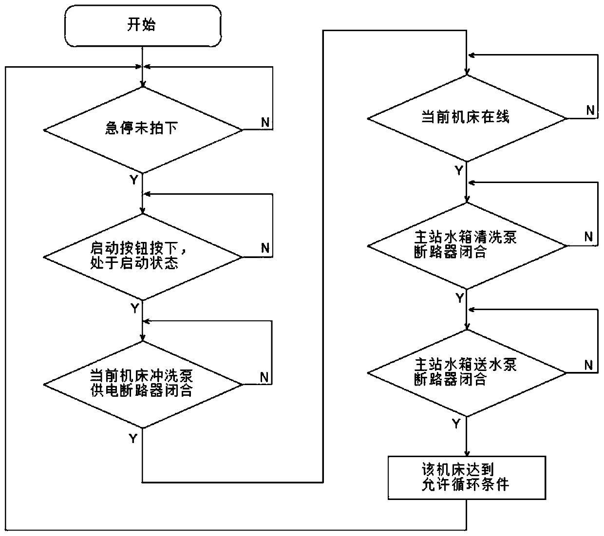
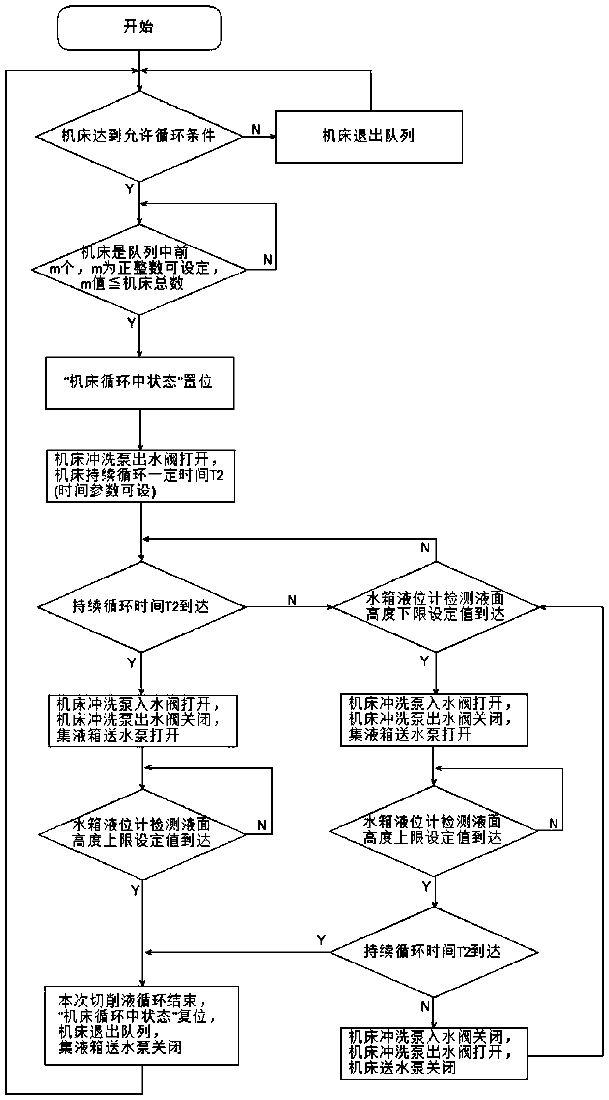
[0047] The present invention is an engraving center cutting fluid centralized processing control system, including n engraving centers and their cutting fluid water tanks, an electrical control cabinet, a liquid collection tank, a main liquid return pipeline and a main liquid delivery pipe Road, each branch cutting fluid circuit, n is a positive integer, among them, each engraving center cutting fluid water tank contains a flushing pump, 3 solenoid valves (water outlet valve, water inlet valve, machine tool flushing valve) and 1 liquid level sensor. The liquid tank includes a water delivery pump, a clean water pump and a liquid level sensor.

[0048] The electrical control cabinet is equipped with n "online / offline" knobs, n is a positive integer, and the "ON / OFF" of each knob indicates whether the cutting fluid of the engraving center water tank participates in automatic circulation.

[0049] ①Install the following components at the water tank of the single engraving center: ...


PUM


Abstract

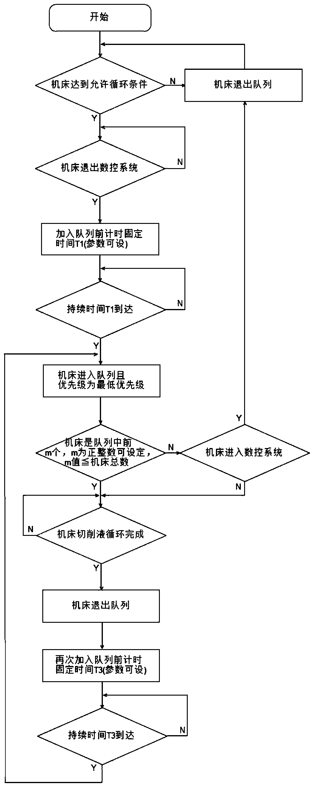
The invention discloses a centralized treatment control method for cutting fluids of carving centers. According to the centralized treatment control method, n carving centers and cutting fluid water tanks thereof, one electrical control cabinet, one fluid collecting tank, one main fluid return pipeline, one main fluid conveying pipeline and all branch cutting fluid loops are involved. The cuttingfluid water tank of each carving center comprises one flushing pump, three electromagnetic valves and one liquid level sensor. The fluid collecting tank internally comprises one water conveying pump,one water purification pump and one liquid level sensor; n online / offline knobs are installed on the electrical control cabinet and used for indicating whether or not the cutting fluids of the water tanks of the corresponding carving centers participate in automatic circulation or not, each single carving center is detected, and whether or not the cutting fluid of the water tank of the carving center participates in system circulation is judged; each single carving center joins in a circulation queue, and the circulation queue is updated; the circulation states of the cutting fluids of the carving centers in the circulation queue are detected, and then material processing begins. By means of the method, full-automatic circular filtering treatment on the waste cutting fluids of multiple carving centers is achieved.

Description

technical field [0001] The invention belongs to the technical field, and in particular relates to a centralized processing control method for cutting fluid in an engraving center. Background technique [0002] With the continuous development of the 3C industry, there are more and more application scenarios of CNC engraving centers, and the number of engraving centers in ordinary processing factories is also increasing. In order to manage these devices more conveniently and effectively, the various engraving centers in the workshop are often placed together for production and processing. In order to save space, the distance between each device is relatively small. As the equipment is used longer, the cutting fluid used in the engraving center will gradually deteriorate and even become smelly. However, the method of centrally placing the engraving centers makes the handling and replacement of the cutting fluid very troublesome. [0003] At present, there are mainly two ways ...

Claims


Application Information

Patent Timeline
IPC IPC(8): B44B1/06B44B3/06
CPCB44B1/06B44B3/06
Inventor 康科穆艺强曹进
Owner 西安精雕软件科技有限公司
Learn More