
anti-tip water cup

A water cup and anti-falling technology, which is applied in the direction of suction cups, drinking vessels, connecting components, etc., can solve the problems of loss of adsorption capacity, wet electronic equipment, and water cup tipping, etc., and achieve the effect of convenient operation, simple structure and good buffering effect

Active Publication Date: 2020-08-18
芜湖锋珉信息科技有限公司
View PDF16 Cites 0 Cited by
  • Summary
  • Abstract
  • Description
  • Claims
  • Application Information

AI Technical Summary

Problems solved by technology

[0002] In daily life, when not paying attention, the water cup is often toppled by horizontal collision, the liquid in the water cup is poured out, and the documents and electronic devices on the desktop are wet, which brings troubles to the daily life of the user
[0003] The general anti-tip water cup will use a suction cup to absorb the water cup on the table, and the water cup can only be easily taken by holding the water cup upwards. The adsorption strength cannot be adjusted. There is only one adsorption strength, so now we need a non-tip-proof water cup that can be adsorbed on the table.

Method used


Image

  • anti-tip water cup
  • anti-tip water cup
  • anti-tip water cup

Examples


Embodiment 1

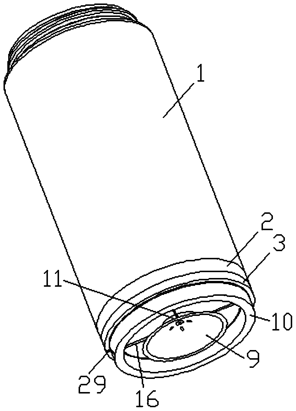
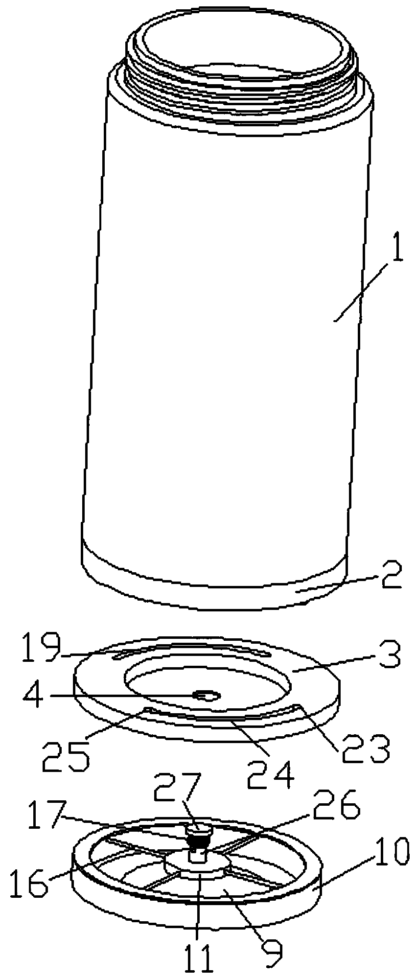
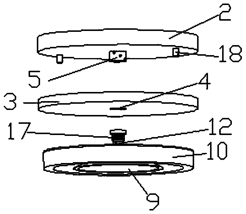
[0035] refer to Figure 1-2 , Figure 4-5 and Figure 8, a preferred embodiment of the present invention will be described in detail below in conjunction with the accompanying drawings. An anti-falling water cup, the vent rod body 26 and the connecting block 11 are integrally injection-molded, and the air pipes 16 of the circular airbag 10 are connected to each other with four ends. The other end passes through the connection block 11 and communicates with the air injection hole 15 on the suction cup 9, and then the suction cup 9 is adhered and fixed on the lower end of the connection block 11, and the release air hole 14 and the L-shaped air hole 13 are closely connected, and the air rod body 26 is connected from the bottom. Pass through the installation hole 4 of the lower cup body 3, the pressure regulating cylinder 5 and the installation hole 4 of the middle cup body 2 upwards in sequence. At this time, the lower end surface of the middle cup body 2 and the upper end surf...

Embodiment 2

[0037] refer to Figure 1-9 , a preferred embodiment of the present invention will be described in detail below in conjunction with the accompanying drawings. In a normal use state, by rotating the upper cup body 1, the upper end of the L-shaped air hole 13 is not facing the first non-pressure hole 6. , when the upper end orifice of the L-shaped air hole 13 is blocked by the inner wall of the pressure regulating cylinder 5, the self-weight of the liquid in the upper cup body 1 and the whole cup body is artificially applied downward pressure when the whole cup body is placed on the desktop , the annular airbag 10 will be deformed, and the gas inside will be squeezed out from the jet hole 15 along the trachea 16, so that the dust or fine particles under the suction cup 9 can be blown away from the position covered by the suction cup 9, which is for the back of the suction cup 9. Adsorption provides a better environment, and then, under the action of pressure, the suction cup 9 c...

Embodiment 3

[0039] refer to Figure 4 and Figure 8 A preferred embodiment of the present invention will be described in detail below in conjunction with the accompanying drawings. An anti-fall water cup makes the entire cup body have no adsorption capacity, and the upper cup body 1 is rotated to drive the hollow slider 18 at the lower end of the middle cup body 2 to slide in a circular arc. Rotate in the rail 19, when the hollow slider 18 slides into the rear groove 25, the upper end opening of the L-shaped air hole 13 in the air rod body 26 is aligned with the first non-pressure hole 6, so that the whole cup body is placed on the table. Press down, the air pressure inside the suction cup 9 communicates with the external atmospheric pressure through the release pore 14, and cannot form a negative pressure to generate adsorption force. In this way, the whole cup body is not much different from a normal water cup, so that the user does not want to use the adsorption force of the water cup....


PUM


Abstract

The invention discloses an anti-falling water cup. The anti-falling water cup comprises an upper cup body, a middle cup body, a lower cup body and adsorption equipment, wherein mounting holes are formed in the centers of the middle cup body and the lower cup body respectively; the bottom of the mounting hole of the middle cup body is fixedly connected with a pressure regulating cylinder; a first pressure-free hole, a second pressure discharging hole and a third pressure discharging hole are spirally distributed in the pressure regulating cylinder from the top to bottom; the adsorption equipment comprises a suction cup, an annular air bag, a connecting block and a T-shaped ventilation rod, wherein the T-shaped ventilation rod is fixedly arranged above the connecting block; an L-shaped air hole is formed in the T-shaped ventilation rod; the upper end of the suction cup is fastened in the connecting block; one release air hole and a plurality of blow holes are formed in the suction cup; an air pipe which penetrates through the connecting block is communicated between the blow holes and the annular air bag; the lower end of the L-shaped air hole penetrates through the connecting blockand the release air hole to be communicated; and the upper end surface of the annular air bag is adhered to the lower end surface of the lower cup body. When the water cup is placed on a table board,suction force is generated, so that falling of the water cup can be prevented, and the suction force of the water cap can be adjusted according to rotation.

Description

technical field [0001] The invention belongs to the technical field of water cups, in particular, the invention relates to an anti-falling water cup. Background technique [0002] In daily life, when not paying attention, the water cup is often toppled due to horizontal collision, and the liquid in the water cup is poured out, which wets the documents and electronic equipment on the desktop, which brings troubles to the daily life of the user. [0003] The general anti-tip water cup will use a suction cup to absorb the water cup on the table. Only by holding the water cup up can you easily take the water cup. The adsorption strength cannot be adjusted, there is only one adsorption strength, so now we need an anti-tip water cup that can be adsorbed on the table. Contents of the invention [0004] The invention provides an anti-falling water cup, which can prevent falling through the adsorption force, and can adjust the magnitude and presence or absence of the adsorption fo...

Claims


Application Information

Patent Timeline
Patent Type & Authority Patents(China)
IPC IPC(8): A47G19/22F16B47/00
CPCA47G19/2261F16B47/00
Inventor 吴正飞宣鹏程王竑喆
Owner 芜湖锋珉信息科技有限公司
Learn More