Weak magnetic field measurement device and method based on modal localization effect

A weak magnetic field and measuring device technology, applied in the direction of the magnitude/direction of the magnetic field, can solve the problems of small dynamic range, difficulty in achieving high precision, affecting device sensitivity and resolution, etc., to achieve enhanced strength and eliminate feedthrough capacitance signals Interference, effects that improve stability and accuracy

Inactive Publication Date: 2019-12-06
NORTHWESTERN POLYTECHNICAL UNIV
View PDF9 Cites 11 Cited by
  • Summary
  • Abstract
  • Description
  • Claims
  • Application Information

AI Technical Summary

Problems solved by technology

[0005] Among the MEMS magnetometers based on the Lorentz force, a class of magnetometers based on amplitude modulation has achieved an ultra-high sensitivity of 30nT / Hz and has a good quality factor, but the disadvantage is that its dynamic range is small. In practical applications, the measurement range is limited, so it is difficult to apply to various scenarios
Compared with the former, another type of magnetometer based on frequency modulation has a better dynamic range, but there is a frequency drift problem in the measurement process, which will greatly affect the sensitivity and resolution of this type of device, and it is difficult to achieve high precision

Method used


Image

  • Weak magnetic field measurement device and method based on modal localization effect
  • Weak magnetic field measurement device and method based on modal localization effect
  • Weak magnetic field measurement device and method based on modal localization effect

Examples


Embodiment Construction

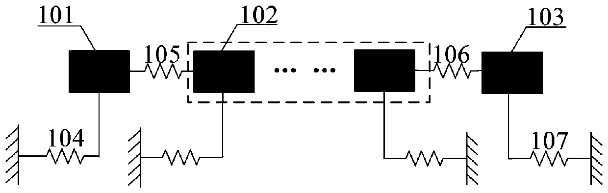
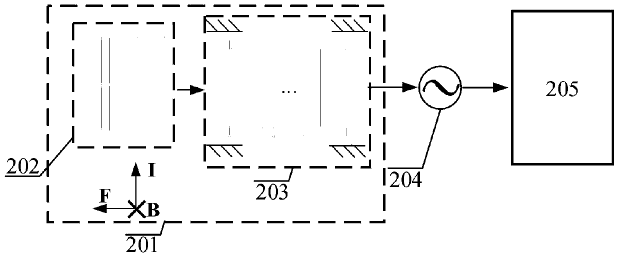
[0029] This embodiment uses a three-degree-of-freedom weakly coupled resonator to implement self-driving in a magnetic field. At the same time, a grid structure is used to greatly change the energy distribution of the resonator array. Combined with a detection circuit, the magnitude of the magnetic field is detected by the amplitude difference between the first and last resonators.

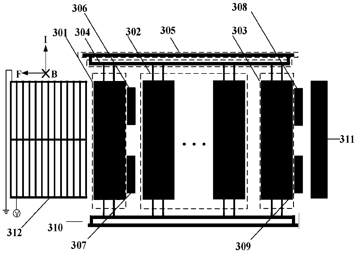
[0030] The high-precision weak magnetic field measurement device in this embodiment mainly includes a weak coupling resonator, a grid structure 312 and an electrode part; the weak coupling resonator includes three identical resonators, resonator one 301, resonator two 303 , and an intermediate resonator, there is a grid structure 312 at 3 μm outside the first resonator 301; the first resonator 301 and the second resonator 303 have exactly the same stiffness, and they are placed sequentially with the intermediate resonator in the horizontal direction; each resonator is The resonant beams in the vert...


PUM


Abstract

The invention discloses a high-sensitivity magnetic field measurement method and device and belongs to the field of an electronic measurement instrument. The device comprises a magnetic field measurement chip and a test signal processing method. The chip comprises at least two weakly coupled resonators, a driving electrode, a detection electrode and an outer gate-type structure. The AC current isapplied to the weakly coupled resonators through a driving electrode, and when the chip is placed in a vertical magnetic field, the resonators are subjected to changed Lorentz force to generate simpleharmonic vibration; when the external magnetic field changes, a vibration state of the resonators changes accordingly, moreover, the DC current is applied to the gate-type structure, the gate-type structure is subjected to Lorentz force in the horizontal direction, and the electrostatic negative stiffness between the gate-type structure and the weakly coupled resonators is changed, so energy distribution of a weakly coupled resonator system is severely unbalanced. Two sets of detection electrodes are designed on two sides of an output resonator, single-resonator amplitude difference detectionis achieved, feed-through capacitance interference is eliminated, and high-sensitivity measurement of the weak magnetic field intensity can be achieved by measuring resonator amplitude difference. The device is advantaged in that real-time measurement of the weak magnetic field can be realized, the anti-interference capability is high, and use significance is high.

Description

[0001] Field: [0002] The invention relates to a high-precision weak magnetic field measuring device under a new theory and a corresponding testing method, belonging to the field of electronic measuring instruments. Background technique [0003] Beginning with Sinan in ancient times, humans have been detecting and applying magnetic field strength for thousands of years. Since modern times, magnetic field strength detection has important application requirements in many fields of scientific research and engineering technology, especially in the field of aerospace navigation systems. A magnetometer is an electronic instrument that can measure the strength and direction of the surrounding magnetic field at the same time, and the magnetometer under the micromechanical electronic process (MEMS) has become the current A hot spot in magnetometer research. [0004] In principle, some MEMS magnetometers use permanent magnets to measure magnetic field strength by combining electron t...

Claims


Application Information

Patent Timeline
Patent Type & Authority Applications(China)
IPC IPC(8): G01R33/02
CPCG01R33/02
Inventor 常洪龙李文牧严子木叶芳
Owner NORTHWESTERN POLYTECHNICAL UNIV
Why Eureka
Try Eureka