Fan and Duct Machine
A fan and air duct technology, which is applied in the field of fans and duct machines, can solve problems such as fan and volute noise, and achieve the effects of solving complex structures, reducing transmission, and improving the noise environment
- Summary
- Abstract
- Description
- Claims
- Application Information
AI Technical Summary
Problems solved by technology
Method used
Image
Examples
Embodiment 1
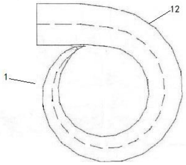
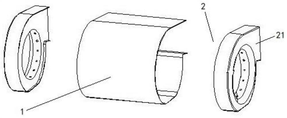
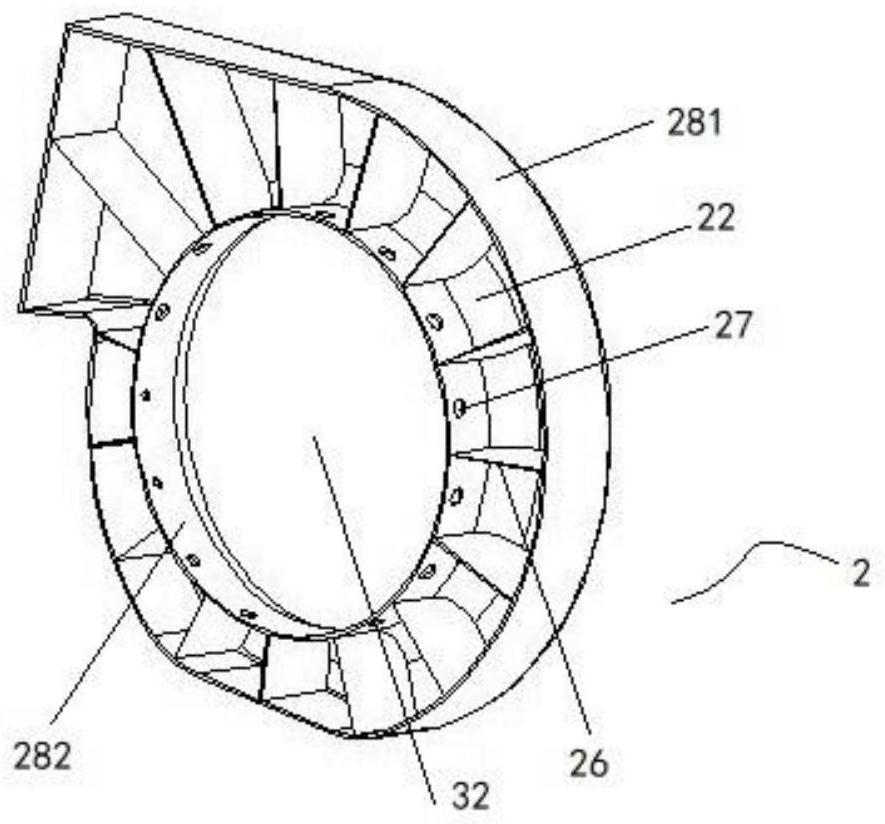
[0036] According to the first aspect of the embodiments of the present invention, another fan is provided, such as Figure 2-3 As shown, it includes the impeller between the volute 1 and the two air inlets 11 arranged on both sides of the volute 1, and also includes one or more noise reducers 2, and each noise reducer 2 is arranged at the inlet of the volute 1. In the air duct at the tuyere 11; each noise reducer 2 includes an annular casing 21 that is closed and adapted to the radial cross-sectional shape of the volute 1, and a plurality of inner peripheral walls along the annular casing 21 are arranged in the annular casing 21. The muffler cavities 22 arranged in sequence in the circumferential direction and separated from each other, each muffler cavity 22 has a through hole 27 communicating with the air inlet 11 .
[0037] In one embodiment of the present invention, the radial cross-sectional shape of the casing of the volute 1 is a spiral shape, and here, the radial direc...
Embodiment 2
[0064] The first aspect of the embodiment of the present invention provides another fan, such as Figure 5-7 As shown, it includes the impeller between the volute 1 and the two air inlets 11 arranged on both sides of the volute 1, and also includes one or more noise reducers 2, and each noise reducer 2 is arranged at the inlet of the volute 1. In the air duct at the tuyere 11; each noise reducer 2 includes an annular casing 21 that is closed and adapted to the radial cross-sectional shape of the volute 1, and a plurality of inner peripheral walls along the annular casing 21 are arranged in the annular casing 21. Circumferentially arranged in sequence, mutually isolated mufflers 22, each muffler 22 has a first through hole 23 communicated with the air inlet 11; each muffler 22 is away from the first through one or more edges The diaphragm 25 arranged at intervals in the direction of the through hole 23 is divided into two or more sound-absorbing sub-cavities 221; The opening p...
Embodiment 3
[0092] In the third embodiment, the present invention also provides a fan, including a volute 1 and an impeller between two air inlets 11 arranged on both sides of the volute 1, and also includes one or more noise reducers 2, more A noise reducer 2 includes at least one noise reducer 2 provided in the first embodiment and at least one noise reducer 2 provided in the second embodiment, and a plurality of noise reducers 2 are sequentially stacked on the axial direction of the volute 1 In the air duct.
[0093] In this way, the two types of noise reducers 2 disclosed in the above two embodiments can be used to jointly achieve the purpose of reducing fan noise, and the number and stacking method of the two types of noise reducers 2 can be adjusted according to actual noise reduction needs.
[0094] According to the second aspect of the third embodiment of the present invention, there is also provided an air duct machine, including one or more of the above-mentioned fans.
PUM
 Abstract
Description
Claims
Application Information
 - R&D
- Intellectual Property
- Life Sciences
- Materials
- Tech Scout
- Unparalleled Data Quality
- Higher Quality Content
- 60% Fewer Hallucinations
Browse by: Latest US Patents, China's latest patents, Technical Efficacy Thesaurus, Application Domain, Technology Topic, Popular Technical Reports.
© 2025 PatSnap. All rights reserved.Legal|Privacy policy|Modern Slavery Act Transparency Statement|Sitemap|About US| Contact US: help@patsnap.com


