
Transtion joint for reducing impacted vibration to rail joint by heavy load train

A transition joint, shock vibration technology

Inactive Publication Date: 2005-01-05
XI AN JIAOTONG UNIV
View PDF0 Cites 0 Cited by
  • Summary
  • Abstract
  • Description
  • Claims
  • Application Information

AI Technical Summary

Problems solved by technology

[0004] The direct harm caused by this impact force is: reduce the service life of the train, reduce the service life of the roadbed, and affect the stability of the vehicle operation
At present, there is no effective means to eliminate this impact in the world

Method used


Image

  • Transtion joint for reducing impacted vibration to rail joint by heavy load train
  • Transtion joint for reducing impacted vibration to rail joint by heavy load train
  • Transtion joint for reducing impacted vibration to rail joint by heavy load train

Examples


Embodiment Construction

[0013] The present invention will be described in further detail below in conjunction with the accompanying drawings.

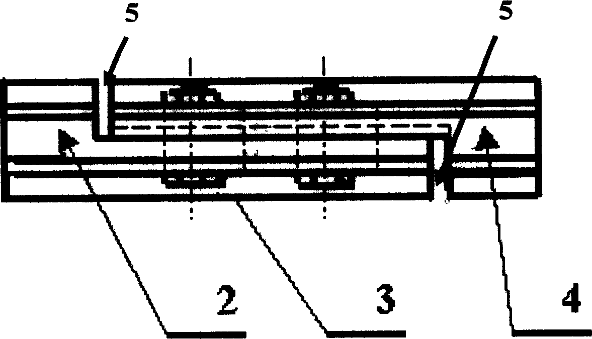
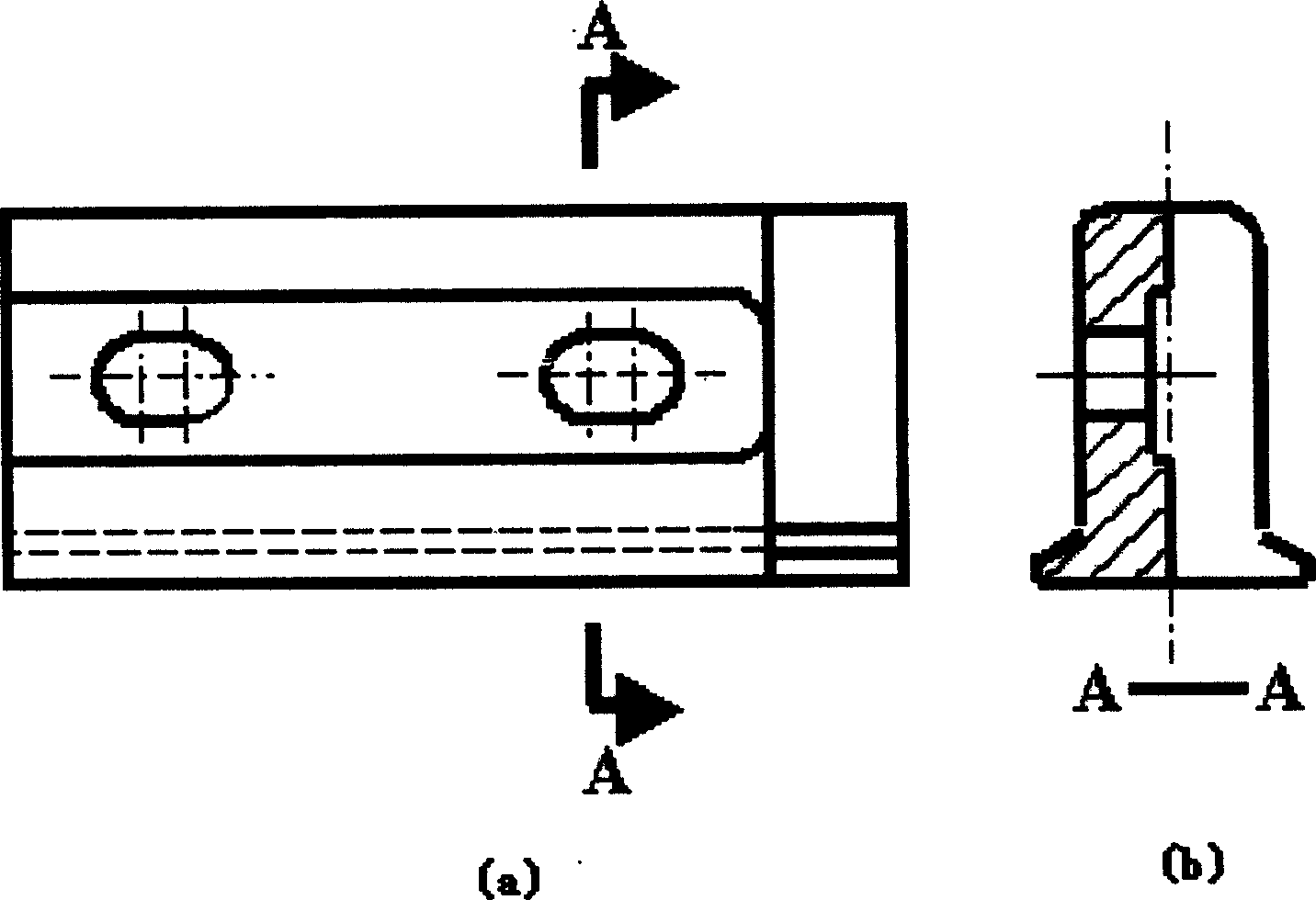
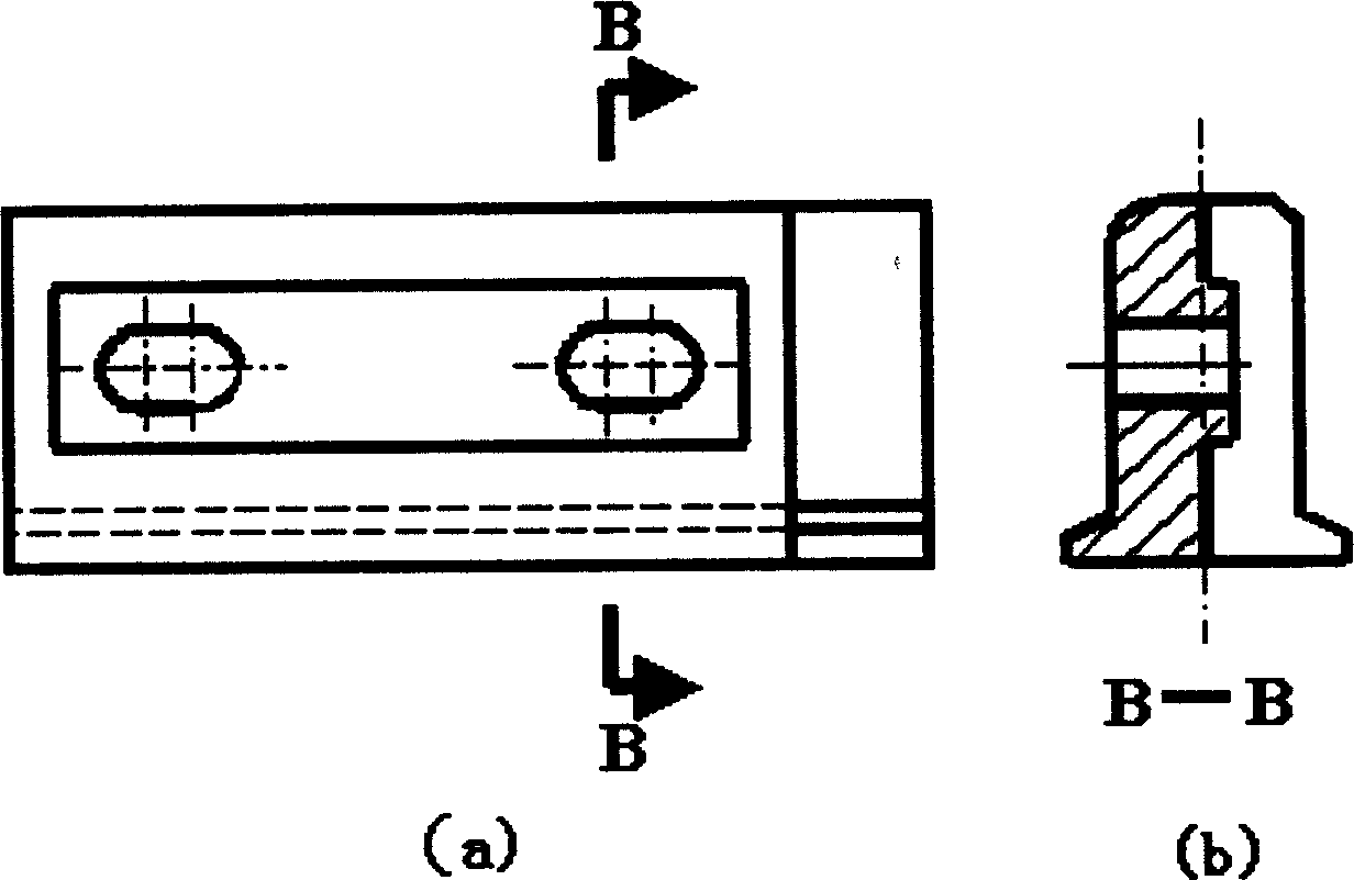
[0014] see Figure 1~3 , a transition joint for reducing impact vibration at rail joints of heavy-duty vehicles. The transition joint is divided into two parts: an outer joint 2 and an inner joint 4. The outer joint 2 and the inner joint 4 have connecting holes respectively, and are connected by bolts 3. There is an expansion joint 5 after the connection.

[0015] The connecting holes on the outer joint 2 and the inner joint 4 are waist-shaped holes.

[0016] The working principle of the present invention is, at the end of former steel rail 1, respectively weld the outer joint 2 of the present invention and the inner joint 4, then the inner joint and the outer joint are connected in the waist-shaped hole with bolts and get final product, (see Figure 4 ). When the wheel passes through the expansion joint at the joint, there is always some part to bear the ...


PUM


Abstract

The invention discloses a transition joint for reducing shock vibration at the joints of the steel rails for heavy load vehicles, adding a transition joint at the joint of existing steel rails, able to play a role of connecting two steel rails and prevent vertical dislocation of the joint. And at the same time, it can also play a role of dividing the load of the train wheels, namely a load-sharing method. It is composed of two parts, one is an inside joint and the other one is an outside joint. That is to say, in the thermal-expanding and cold-contracting space at the joint, when the wheel passes through an expansion joint at the joint, there is always some part to bear the wheel weight to ensure the wheel to run stably. When the vehicle runs stably, there is no shock vibration between the wheel and the steel rails, thus improving the safety of vehicles and prolonging the service life of road foundation.

Description

technical field [0001] The invention belongs to the technical fields of vibration and noise control and mechanical manufacturing, and in particular relates to a transition joint for reducing impact vibration at rail joints of heavy-duty vehicles. Background technique [0002] At present, there is no effective method for reducing the collision between the wheels and the rails of the vehicle during operation at the rail joints of the relevant heavy-duty vehicles. In order to reduce the impact between the wheels and the rails, the current method is to weld the original short rails into 5-10 kilometers long rails. Due to the thermal expansion and contraction of the rails, it is impossible to completely eliminate the rails during roadbed construction. If the joint is used, the impact vibration of the wheel and the rail at the rail joint cannot be completely eliminated. [0003] At present, in the construction of railways at home and abroad, in order to solve the problem of therm...

Claims


Application Information

Patent Timeline
Patent Type & Authority Applications(China)
IPC IPC(8): E01B11/24
Inventor 张铁山樊克俊黄协请
Owner XI AN JIAOTONG UNIV
Learn More