
Fan active noise control system and method based on virtual error sensing

A technology of active noise control and virtual sensing, which is applied in the direction of sound-emitting devices and instruments, and can solve problems such as installation restrictions of electro-acoustic devices, cost loss, and inability to effectively control low-frequency noise

Pending Publication Date: 2021-06-08
西安艾科特声学科技有限公司
View PDF0 Cites 0 Cited by
  • Summary
  • Abstract
  • Description
  • Claims
  • Application Information

AI Technical Summary

Problems solved by technology

On the one hand, due to the limitation of passive noise control technology, low-frequency noise cannot be effectively controlled. On the other hand, passive noise control technology usually changes the structure and design of the product itself, which will cause great damage to products that have been mass-produced or finalized. cost loss
[0004] Optimizing the noise of the fan through active noise control technology can effectively avoid the above problems caused by passive noise reduction, but the active noise control technology needs to pick up the noise signal in the noise reduction area, and the internal structure of the fan makes the electroacoustic device ( error microphone) are severely restricted
In order to solve the common problems of passive and active noise control technologies, this invention proposes an active noise control system based on virtual error sensing to optimize the noise of the fan, which not only avoids cost loss, but also solves the limitation that the error microphone cannot be installed

Method used


Image

  • Fan active noise control system and method based on virtual error sensing
  • Fan active noise control system and method based on virtual error sensing
  • Fan active noise control system and method based on virtual error sensing

Examples


Embodiment 1

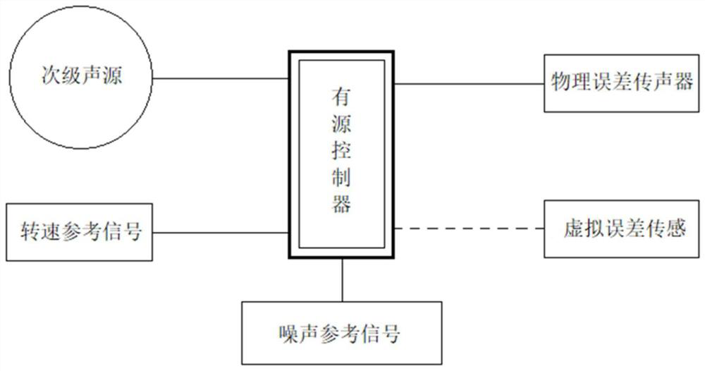
[0031] Such as figure 1 A fan active noise control system based on virtual error sensing is shown, including: an active controller and a secondary sound source connected to the active controller, a physical error microphone, a virtual error sensor, and a speed reference signal , noise reference signal, and a fan model and a pipeline connected to the fan model are also established. A plurality of the physical error microphones are installed on the fan, and a plurality of virtual sensing positions are evenly distributed on the fan, and the secondary sound source is arranged on the fan. and on the pipeline.

[0032] The active controller: the main function is to receive the input signal picked up by the physical error sensor, first preprocess the signal, calculate the transfer function from the physical error microphone to the virtual sensing position, and estimate the virtual error sensor through the transfer function Then the controller takes the signal at the virtual sensor a...

Embodiment 2

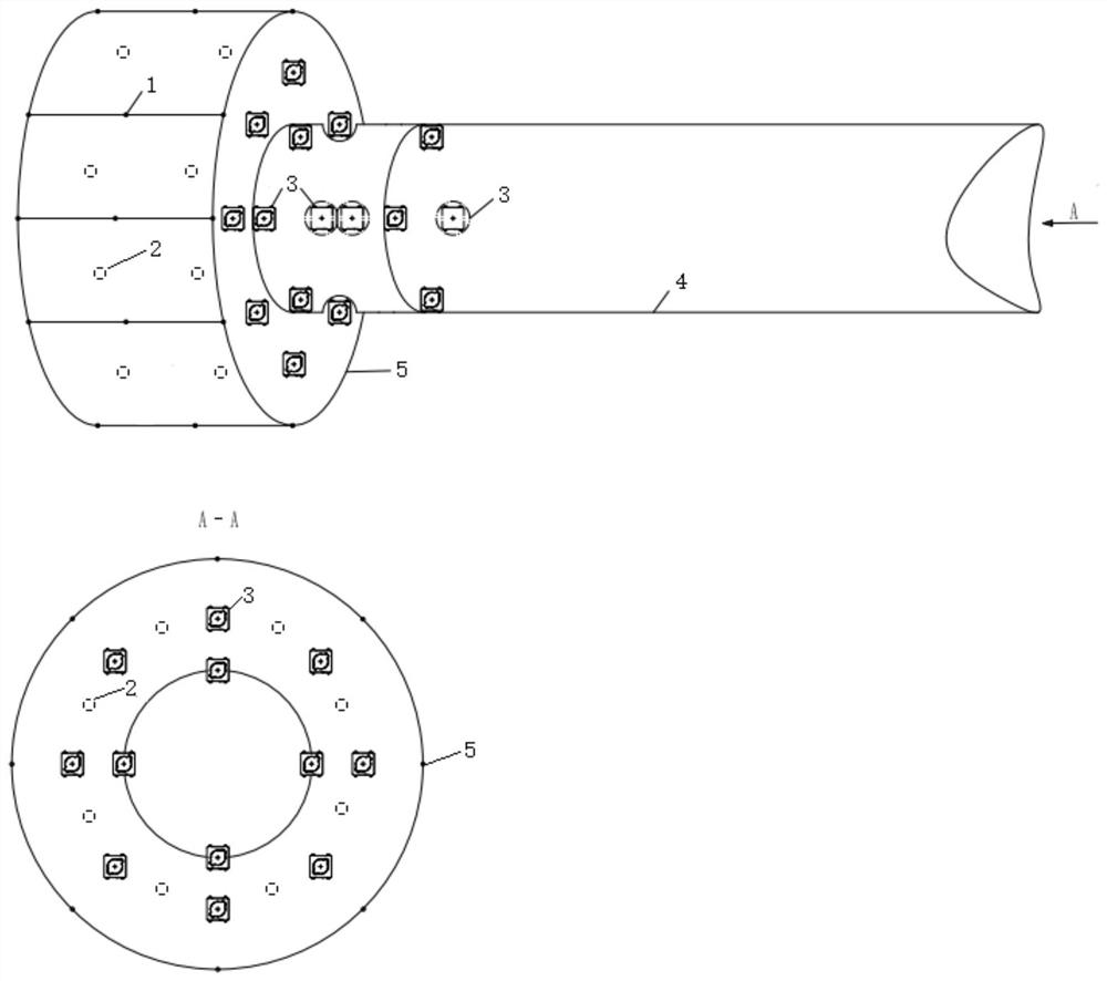
[0039] Such as figure 2 As shown, the positions of the physical error microphone 1 and the virtual sensing are arranged around the control area in a surrounding manner, that is, multiple physical error microphones are installed on the side of the fan, and a plurality of virtual sensing positions are evenly distributed on the side of the fan. The secondary sound source is arranged on the casing of the fan and the nearby pipelines.

[0040] The system is not limited to figure 2 Fan duct model shown, other fan types still applicable;

[0041] The location and number of secondary sound sources and physical error microphones in the fan duct are just examples and not limited to figure 2 The position and number shown;

[0042] The reference signal adopts the combined reference signal of speed and noise for the first time, but it is not limited to speed and noise;

[0043] The location and number of virtual error sensors are examples and are not limited to figure 2 location and...

Embodiment 3

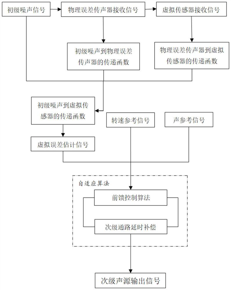
[0045] Such as image 3 As shown, an active noise control method for wind turbines based on virtual error sensing first collects the primary noise signal through the physical error microphone, calculates the acoustic transfer function from the primary noise to the physical error microphone, and then takes the signal at the physical error microphone as input , the signal at the virtual error sensor is used as the output signal, and the acoustic transfer function from the physical error microphone to the virtual error sensor is estimated by the built-in algorithm of the active controller, and then the acoustic transfer function from the primary noise to the virtual error sensor is calculated, and then Estimate the noise signal in the virtual error sensing area as the control target, and perform noise control through the built-in adaptive algorithm of the active controller to obtain a secondary sound source signal equal to the target noise and opposite in phase, and then sent to t...


PUM


Abstract

The invention discloses a fan active noise control system and method based on virtual error sensing. The system comprises an active controller, as well as secondary sound sources, physical error microphones, a virtual error sensor, a rotating speed reference signal and a noise reference signal which are connected with the active controller; a fan model and a pipeline connected with the fan model are established; the multiple physical error microphones are installed on the fan; multiple virtual sensing positions are evenly distributed on the fan; and the secondary sound sources are arranged on the fan and the pipeline. According to the fan active noise control system and method based on the virtual error sensing of the invention, the installation problem of the microphones in a target area is effectively solved by adopting a virtual error sensing technology; a noise control area is arranged in the fan, the positions of the physical error microphones and virtual sensors are arranged near the control area in a surrounding mode, and therefore, the spatial layout is reasonable, and accurate input signals are provided for a control target; noise control is carried out from the aspects of the noise source and the transmission process, the noise environment of the fan is optimized, and the overall performance of a product is improved.

Description

technical field [0001] The invention relates to the technical field of fan active noise control, and more specifically relates to a fan active noise control system and method based on virtual error sensing. Background technique [0002] Fan is a mechanical abbreviation for gas compression and gas delivery. The structure of a general fan includes a casing and an internal structure. The casing is generally connected to the pipeline, and the pipeline is the necessary structure for the fan to compress or transport gas; the internal structure of the fan mainly includes impeller blades, brackets, couplings, transmission systems, power systems, etc. Fans are used in a wide range of fields, such as metallurgy, electric power, ships, urban rail transit, indoor ventilation systems, etc. With gas as the medium, the machine that can transfer mechanical energy to the gas, increase the pressure of the gas and suck or press the gas is called a fan. [0003] With the continuous digestion ...

Claims


Application Information

Patent Timeline
IPC IPC(8): G10K11/178
CPCG10K11/1781G10K11/17813G10K11/17817G10K11/1787
Inventor 代海张亚洲党晨李鑫玉昊昕
Owner 西安艾科特声学科技有限公司
Learn More