A chamfering tool for research and development of optical parts

A technology of optical parts and chamfering tools, which is applied in the direction of manufacturing tools, grinding/polishing equipment, grinding machine parts, etc., can solve the problems of long processing cycle affecting experiments, etc., and achieve the effect of small size and good grinding accuracy

Active Publication Date: 2021-06-22
江苏聚冠新材料科技有限公司
View PDF0 Cites 0 Cited by
  • Summary
  • Abstract
  • Description
  • Claims
  • Application Information

AI Technical Summary

Problems solved by technology

[0003] Existing lenses often need to be assembled on various testing instruments during the research and development process, and the grinding process of the lens is often completed by the lens manufacturer. In some small laboratories, the lens often needs to be placed in various types of experiments On the instrument, the edge of the lens edge needs to be adjusted frequently. If the lens is sent back to the manufacturer for processing, there will be a problem that the processing cycle will be too long and the experiment will be affected.

Method used


Image

  • A chamfering tool for research and development of optical parts
  • A chamfering tool for research and development of optical parts
  • A chamfering tool for research and development of optical parts

Examples


Embodiment Construction

[0030] The following will clearly and completely describe the technical solutions in the embodiments of the present invention with reference to the accompanying drawings in the embodiments of the present invention. Obviously, the described embodiments are only some, not all, embodiments of the present invention. Based on the embodiments of the present invention, all other embodiments obtained by persons of ordinary skill in the art without making creative efforts belong to the protection scope of the present invention.

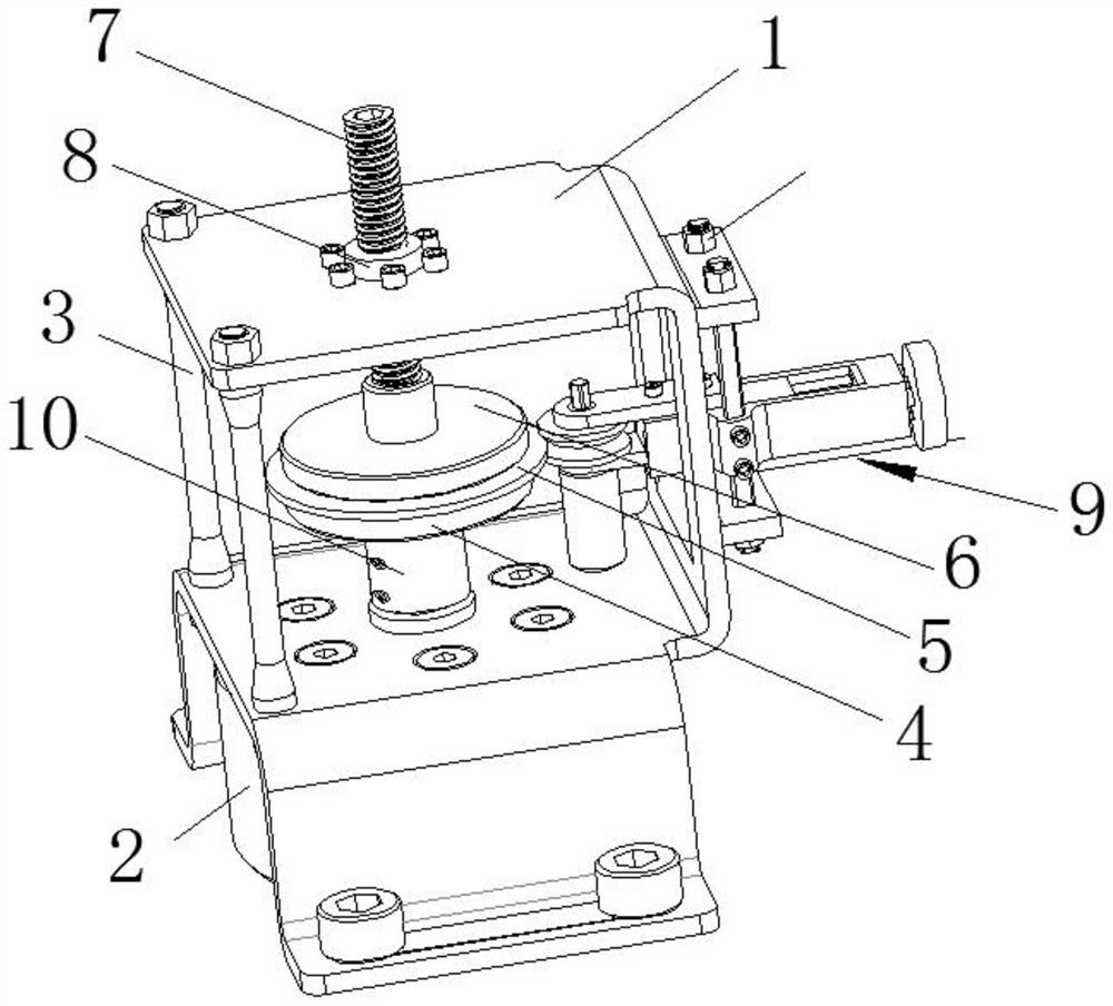
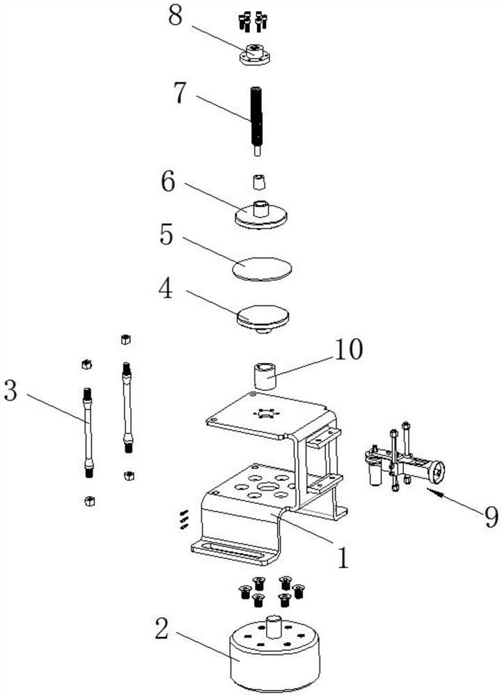
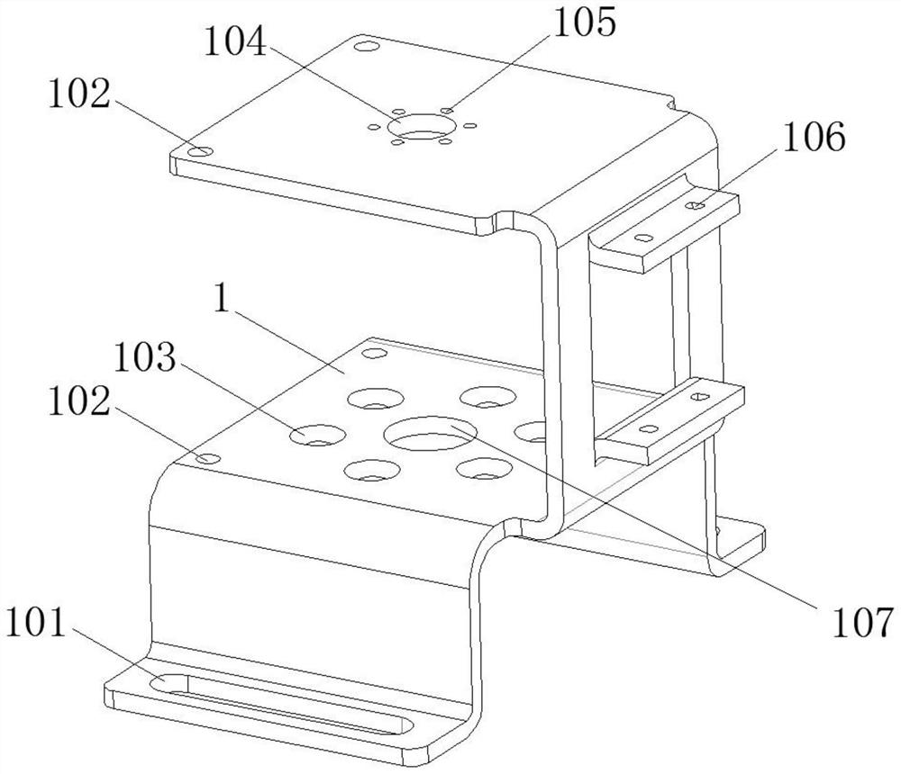
[0031] The present invention provides such Figure 1-16 A chamfering tool for research and development of optical parts is shown, including a main frame body 1, a motor 2, a support rod 3, a lower tray 4, a lens 5, an upper tray 6, a final shaft 7, a threaded flange 8, and a grinding device 9 and the shaft coupling 10, two groups of bottom grooves 101 are opened on the horizontal part of the lower end of the main frame body 1, and frame holes 102, motor holes ...


PUM


Abstract

The invention discloses a chamfering tool for research and development of optical parts, which comprises a main frame body, a motor, a support rod, a lower tray, a lens, an upper tray, a final shaft, a threaded flange, a grinding device and a shaft coupling. There are two sets of bottom grooves on the horizontal part of the lower end of the frame body, frame holes, motor holes and motor shaft holes are opened on the horizontal part of the middle part of the main frame body, and two groups of horizontal grooves bent on the side wall of the main frame body There are eccentric shaft holes on some parts, frame holes, flange holes and flange threaded holes are opened on the horizontal surface of the upper end of the main frame body, and the motor passes through the motor hole through the screw to enter the inside of the threaded hole above it and The main frame body is fixed, the output shaft of the motor passes through the motor shaft hole of the main frame body, a coupling is fixed on the output shaft of the motor through screws, and the upper end of the coupling is sleeved on the lower side of the lower tray on the axial structure. The chamfering cutter used for research and development of optical parts can quickly chamfer optical lenses and is suitable for general promotion and use.

Description

technical field [0001] The invention belongs to the technical field of research and development of optical parts, and in particular relates to a chamfering tool for research and development of optical parts. Background technique [0002] Optical parts are also called optical components. The basic building block of an optical system. Most of the optical components play the role of imaging, such as lenses, prisms, mirrors, etc. In addition, there are some parts that play special roles in the optical system, such as light splitting, image transmission, filtering, etc., such as reticles, optical filters, and gratings for optical fiber parts. Holographic lenses, gradient index lenses, and binary optical elements are new types of optical components that have emerged in the past ten or twenty years. [0003] Existing lenses often need to be assembled on various testing instruments during the research and development process, and the grinding process of the lens is often complete...

Claims


Application Information

Patent Timeline
Patent Type & Authority Patents(China)
IPC IPC(8): B24B9/14B24B47/12B24B47/20
CPCB24B9/14B24B9/146B24B47/12B24B47/20
Inventor 戚志洋
Owner 江苏聚冠新材料科技有限公司
Why Eureka
Try Eureka