
A fuel injection valve and engine

A technology of fuel injection valve and injection valve body, which is applied to fuel injection devices, engine components, machines/engines, etc. problem, to achieve the effect of shortening the shutdown delay time and improving the response speed

Active Publication Date: 2020-11-03
FAW JIEFANG AUTOMOTIVE CO
View PDF7 Cites 0 Cited by
  • Summary
  • Abstract
  • Description
  • Claims
  • Application Information

AI Technical Summary

Problems solved by technology

[0004] In the prior art, there is only one oil inlet hole connected between the control chamber and the high-pressure chamber, resulting in a relatively slow oil inlet speed when the high-pressure oil in the high-pressure chamber enters the control chamber, and the delay time for closing the fuel injection valve is long. The nozzle hole closes slowly, which affects the working performance of the engine

Method used


Image

  • A fuel injection valve and engine
  • A fuel injection valve and engine
  • A fuel injection valve and engine

Examples


Embodiment 1

[0043] This embodiment provides an engine, and the engine includes a fuel injection valve, and the fuel injection valve is used to inject fuel into the combustion chambers of each cylinder of the engine.

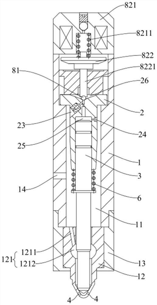
[0044] see Figure 1-Figure 6 , The fuel injection valve provided in this embodiment includes an injection valve body 1 , a valve sleeve 2 and a needle valve 3 .

[0045] The injection valve body 1 has a high-pressure chamber 11 for containing fuel, and an oil inlet 14 communicating with the high-pressure chamber 11 is opened on the side wall of the injection valve body 1 , and the fuel enters the high-pressure chamber 11 through the oil inlet 14 . There are openings at both ends of the high-pressure chamber 11, one end opening of the high-pressure chamber 11 is blocked by the valve sleeve 2, and the other end is provided with a nozzle 12, and the end of the nozzle 12 is provided with a spray hole 4, which can be selectively opened or closed , so that the fuel injection val...

Embodiment 2

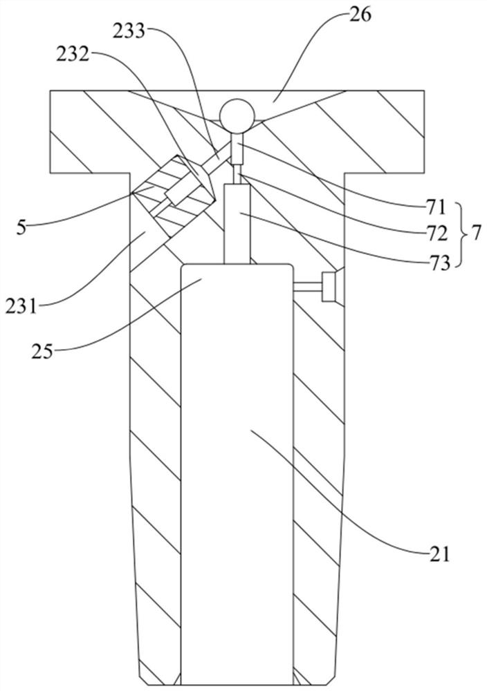
[0068] see Figure 7 The difference between this embodiment and Embodiment 1 is that the oblique oil outlet orifice 23 includes a second counterbore 234, a second tapered hole 235, a transition hole 236 and a second orifice 237 connected in sequence, The second counterbore 234 is directly communicated with the high-pressure chamber 11, the large end opening of the second tapered hole 235 communicates with the second counterbore 234, the small end opening of the second tapered hole 235 is connected with the transition hole 236, and the second throttling The diameter of the hole 237 is smaller than that of the transition hole 236 . Specifically, in this embodiment, the second throttle hole 237 communicates with the upper counterbore 71 of the oil outlet hole 7 .

[0069] In this embodiment, when the electromagnet 821 is powered off, the sealing steel ball 81 is pressed on the sealing cone surface of the conical low-pressure chamber 26 and the upper end of the oil outlet hole 7 ...


PUM


Abstract

The invention discloses a fuel injection valve and an engine, and belongs to the technical field of engines, and the fuel injection valve comprises an injection valve body which is provided with a high-pressure cavity for accommodating fuel oil; a valve sleeve which is arranged in the high-pressure cavity, wherein a containing cavity is formed in the valve sleeve; and a needle valve which is arranged in the high-pressure cavity, wherein one end is located in the containing cavity and the needle valve is matched with the containing cavity to form a control cavity, and the other end of the needle valve is located at the end, away from the control cavity, of the high-pressure cavity; an oblique oil outlet throttling hole is formed in the valve sleeve; an oil inlet throttling hole is formed inthe other side, opposite to the oblique oil outlet throttling hole, of the valve sleeve, the oblique oil outlet throttling hole and the oil inlet throttling hole enable the high-pressure cavity and the control cavity to be in one-way communication, the hydraulic pressure of the end, located in the control cavity, of the needle valve is increased, and then the needle valve is pushed to move so that the needle valve can close the fuel injection valve. The engine is provided with the fuel injection valve. The fuel injection valve can be quickly closed.

Description

technical field [0001] The invention relates to the technical field of engine fuel injection, in particular to a fuel injection valve and an engine. Background technique [0002] Fuel injection valves are generally installed in fuel engines. [0003] The fuel injection valve is used to inject fuel into the combustion chamber of each cylinder of the fuel engine. A needle valve is generally arranged in the fuel injection valve, and the needle valve is located in the high-pressure chamber and can open and close the injection hole of the fuel injection valve. Generally, the movement of the needle valve causes the needle valve to open or close the injection hole of the fuel injection valve. The needle valve part is located in the high-pressure cavity of the fuel injection valve and can block the injection hole, and the other part is located in the control cavity of the valve sleeve of the fuel injection valve. There can be a pressure difference in the hydraulic pressure, and t...

Claims


Application Information

Patent Timeline
Patent Type & Authority Patents(China)
IPC IPC(8): F02M61/10F02M61/16F02M61/18
CPCF02M61/10F02M61/16F02M61/1886
Inventor 喻鸣显金昱森徐亚磊王凌云顾小磊张建刚王华
Owner FAW JIEFANG AUTOMOTIVE CO
Learn More