A self-moving drilling site gangue extraction device

A self-moving, drilling field technology, used in earth-moving drilling, mining equipment, tunnels, etc., can solve the problems of low labor efficiency, high labor intensity of employees, and high labor consumption, and achieve simple installation procedures and improve gangue efficiency. , the effect of reducing the intensity

Active Publication Date: 2020-10-09
HUAINAN MINING IND GRP
View PDF15 Cites 0 Cited by
  • Summary
  • Abstract
  • Description
  • Claims
  • Application Information

AI Technical Summary

Problems solved by technology

[0003] The technical problem to be solved by the present invention is that about 1 / 3 of the gangue in the drilling field cannot be shipped by fully-mechanized excavators, and manual gangue removal is required. In the process of manual gangue removal, manual second turning of gangue is required, and the labor intensity of workers is high. Labor efficiency is low, requiring a lot of manpower

Method used


Image

  • A self-moving drilling site gangue extraction device
  • A self-moving drilling site gangue extraction device
  • A self-moving drilling site gangue extraction device

Examples


Embodiment 1

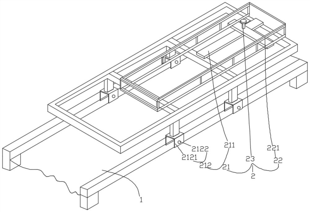
[0047] Such as figure 1 As shown, a self-moving drilling site gangue extraction device includes a belt conveyor 1 and a gangue extraction device 2, and the gangue extraction device 2 is arranged at the tail of the belt conveyor 1;

[0048] The gangue-discharging device 2 includes a mounting bracket 21, a gangue-discharging conveyor 22 and a connector 23. The mounting bracket 21 is erected at the tail of the belt conveyor 1, and the gangue-discharging conveyor 22 is installed on the mounting bracket 21 through the connector 23, and the gangue-discharging conveying The width of the machine 22 is less than or equal to the width of the mounting bracket 21 . The gangue conveyor 22 includes a frame 221 and a gangue belt, and the gangue belt is arranged above the frame 221 .

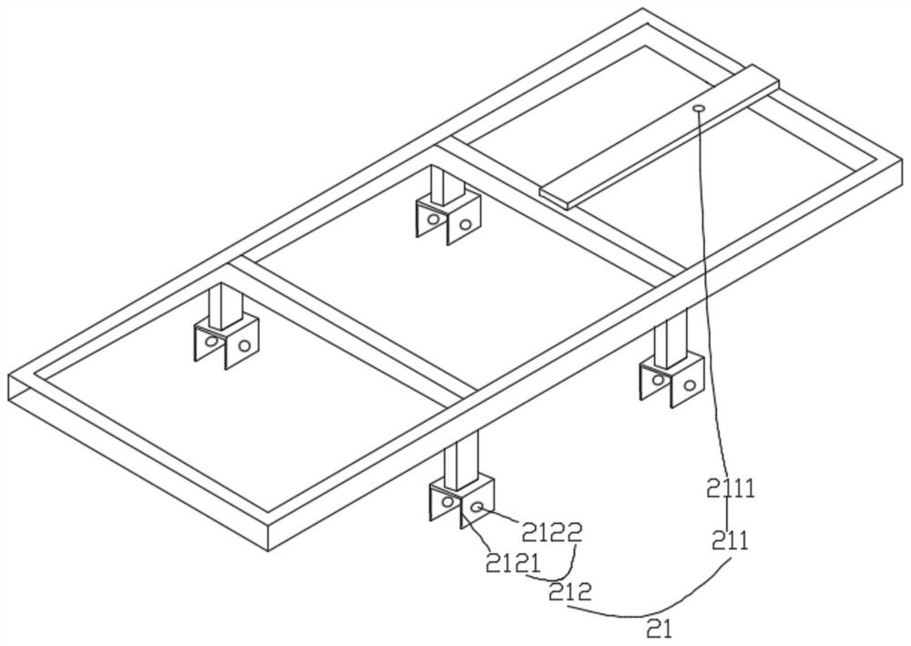
[0049] Such as figure 2 As shown, the mounting bracket 21 is a frame hollow structure, the bottom of the mounting bracket 21 is provided with a mounting leg 212, and the bottom of the mounting leg 212 is pro...

Embodiment 2

[0056] On the basis of Example 1, through 10cm

[0057] Further, L2=L3, that is, the connecting piece 23 is arranged on the horizontal midline of the installation bracket 21 .

Embodiment 3

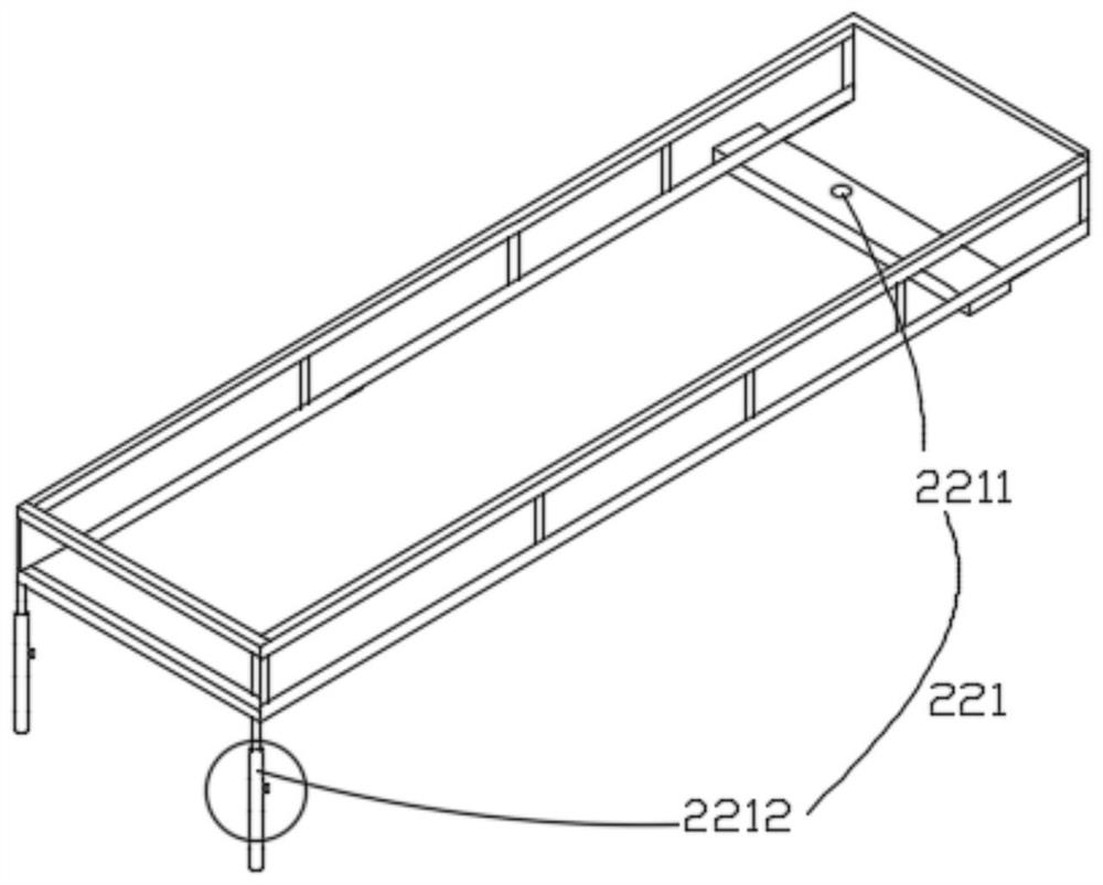
[0059] Such as image 3 with Figure 7 As shown, the frame 1 is provided with a foldable support leg 2212 near the bottom, and the bottom of the frame 221 is provided with a support leg placement groove 2213, and the support leg placement groove 2213 is used to place the folded support leg 2212. When discharging gangue, the gangue conveyor 21 is rotated to a suitable position by adjusting the connecting piece 23, and the supporting leg 2212 in the supporting leg placement groove 2213 is taken out, and the frame 221 not only fixes and supports the output end through the connecting piece 23 in the installation On the support 21, the input end of the frame 221 is supported by the supporting legs 2212 at the same time, so as to improve the stability of the gangue-discharging device. When the use of the gangue-discharging device is finished, the supporting legs 2212 are folded and placed in the supporting-leg placement groove 2213, so as to reduce the occupied space of the support...


PUM


Abstract

The invention discloses a self-moving drill-field rock discharging device and relates to a rock discharging device. The self-moving drill-field rock discharging device comprises a belt conveyor and the rock discharging device, wherein the rock discharging device is arranged at the tail of the belt conveyor, and comprises a mounting bracket, a rock discharging conveyor and a connector; the mountingbracket is erected at the tail of the belt conveyor; through the connector, the rock discharging conveyor is arranged on the mounting bracket; the width of the rock discharging conveyor is less thanor equal to that of the mounting bracket; the mounting bracket is of a hollow framework structure; a rock dropping point is formed in the gap between the output end of the rock discharging conveyor and the side edges of the belt bracket; and the rock discharging conveyor is capable of rotating in the horizontal plane with the connector as a pivot. According to the self-moving drill-field rock discharging device, the rock discharging conveyor is connected with the mounting bracket through the connector and rotated to the rock discharging position, so that the rock conveying process can be completed as long as rocks are manually turned to the rock discharging conveyor, flow out of the rock discharging conveyor and enter the belt conveyor; and after the rocks in a drill field are discharged,the rock discharging conveyor is rotated to the conveying position and the automatic rock discharging device moves forward along with the pull movement of the tail of the belt conveyor, so that the self-moving effect can be achieved.

Description

technical field [0001] The invention belongs to the field of gangue ejection devices, and in particular relates to the field of gangue ejection devices for self-moving drilling sites. Background technique [0002] The gas drainage roadway is designed with a drilling field. During the construction of the fully mechanized excavation at the drilling field, due to the limitation of the rotation radius of the cutting arm of the fully mechanized excavator, many waste rocks in the drilling field cannot be reached by the rotation of the cutting arm of the fully mechanized excavator, resulting in About 1 / 3 of the gangue cannot be shipped by fully mechanized excavators, and it needs to be extracted manually. When the gangue is manually extracted, it needs to be transported with a belt conveyor. When extracting gangue manually, it is first necessary to turn the gangue from the drilling site to a position closer to the belt conveyor, and then manually turn the gangue near the belt conve...

Claims


Application Information

Patent Timeline
Patent Type & Authority Patents(China)
IPC IPC(8): E21D9/12
CPCE21D9/12
Inventor 成兆庆臧升明段于雷牛新国张国老
Owner HUAINAN MINING IND GRP
Why Eureka
Try Eureka