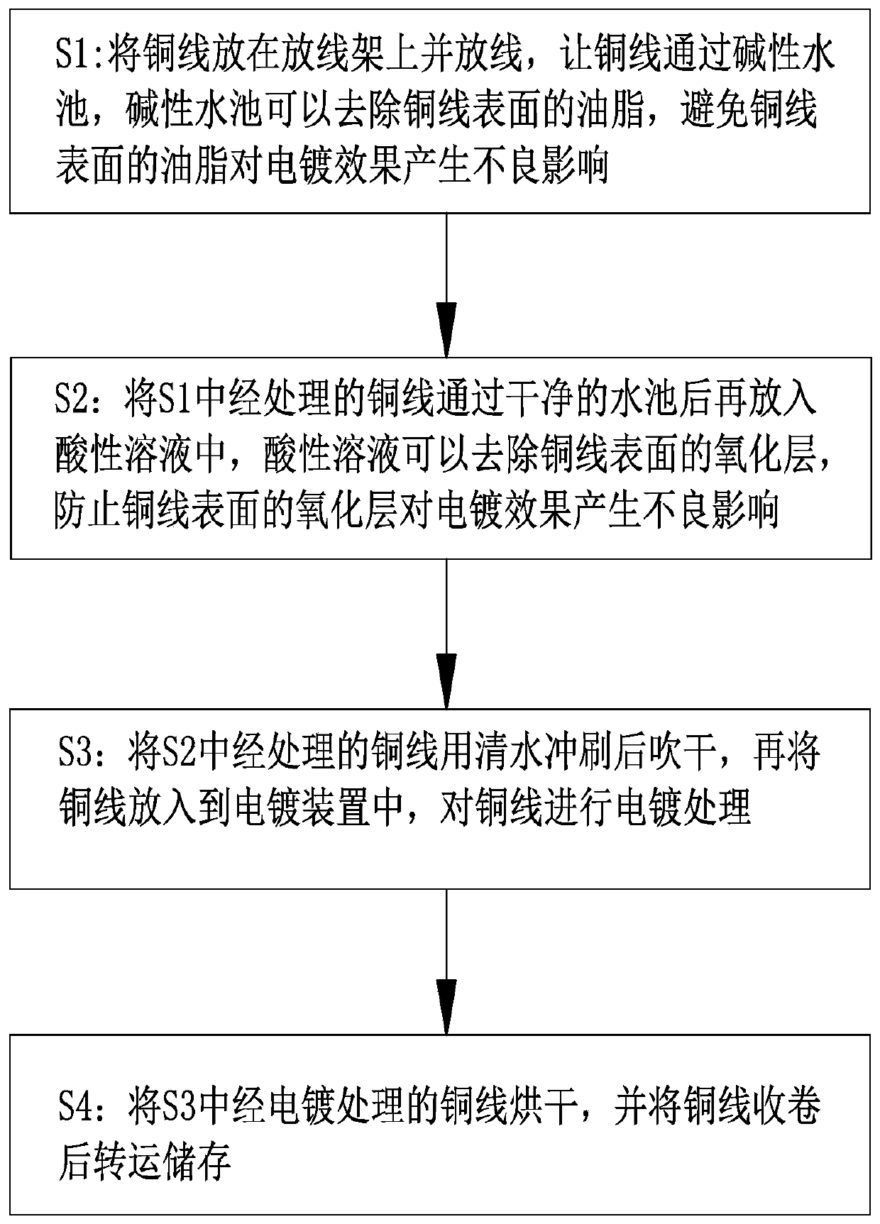
Tinned copper wire electroplating method
A tinned copper wire and copper wire technology, applied in the electrolysis process, electrolysis components, grinding machines, etc., can solve the problems of poor copper wire electroplating effect, copper wire electroplating failure, insufficient copper wire surface treatment, etc., to improve the electroplating quality , Improve the effect of electroplating and avoid the effect of electroplating failure
- Summary
- Abstract
- Description
- Claims
- Application Information
AI Technical Summary
Problems solved by technology
Method used
Image

Examples
Embodiment approach
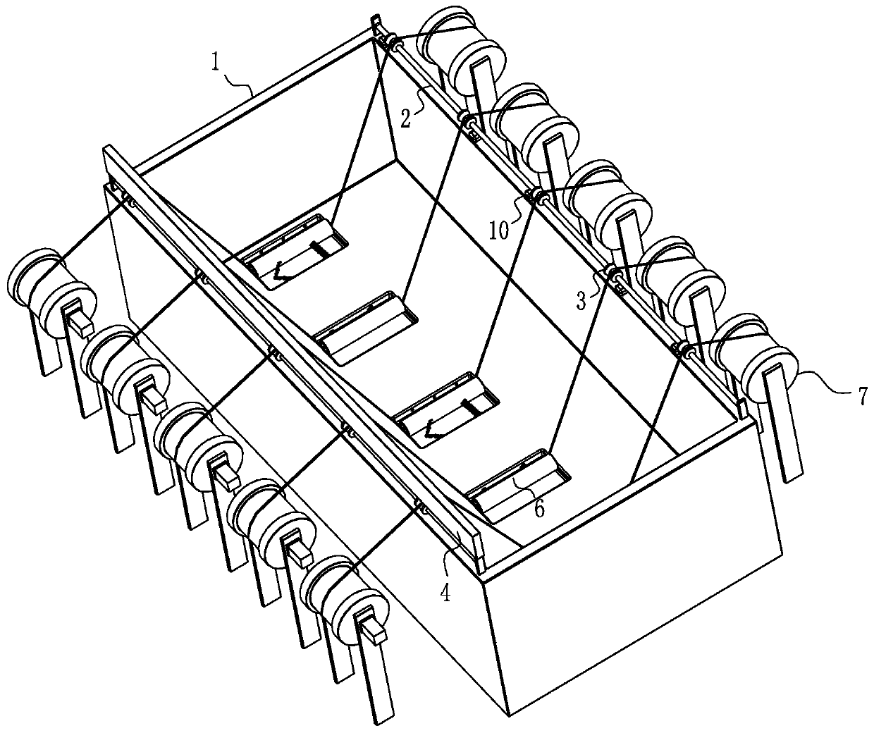
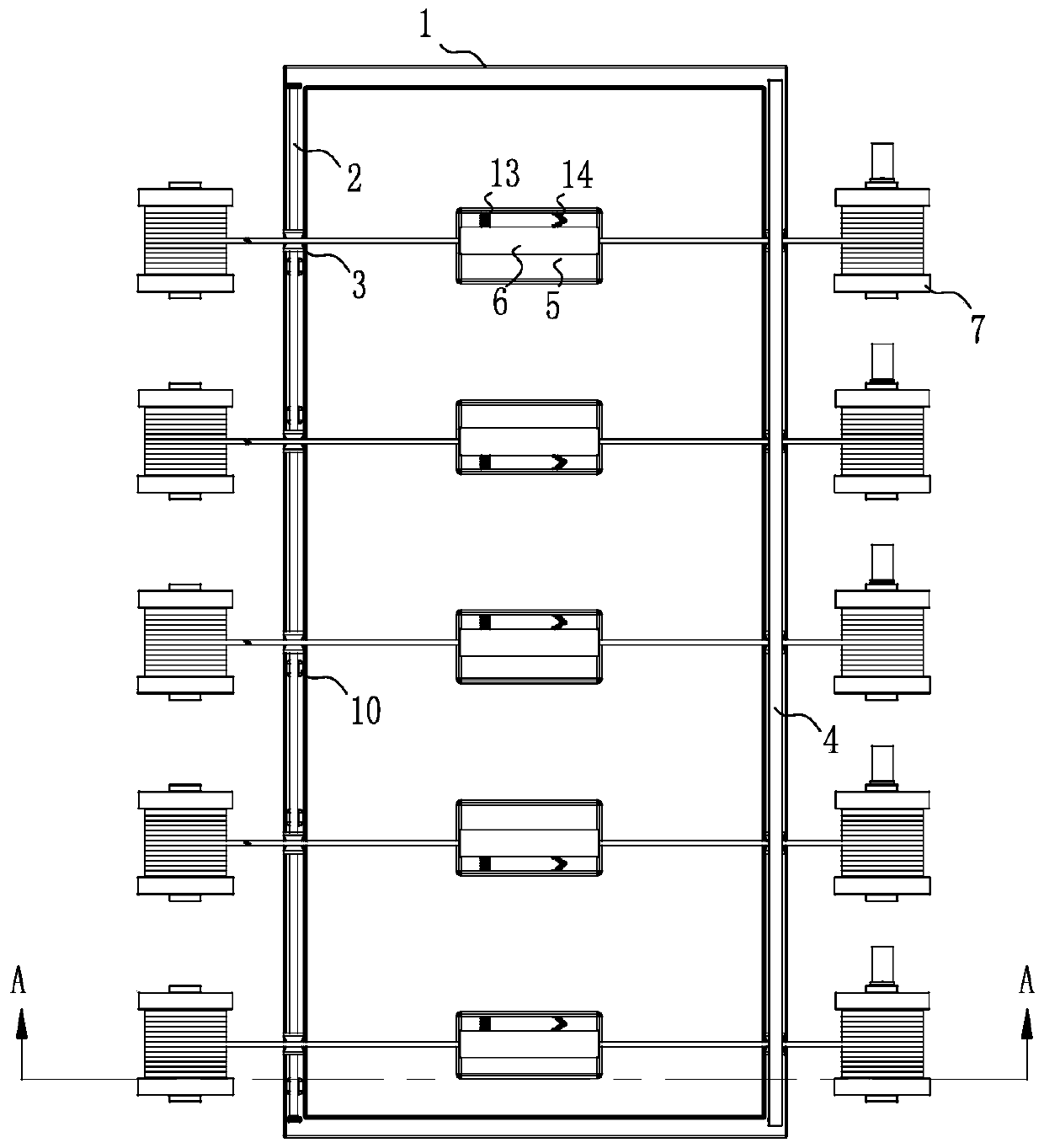
[0036] As a specific embodiment of the present invention, the top side of the electroplating pool 1 is provided with a plurality of L-shaped air holes, the top of the air holes is fixed with a push rod motor 10, the output shaft end of the push rod motor 10 is fixed with a piston 11, and the piston 11 is closely attached to the side wall of the air hole. The end of the air hole facing the bottom of the electroplating pool 1 is provided with a plurality of air vents 12. The air vents 12 are arranged tangentially. The air vents 12 communicate with the rectangular groove 5. The top of the electroplating pool 1 extends to the bottom of the electroplating pool 1 along the side wall of the electroplating pool 1, and the side where the air hole is located at the bottom of the electroplating pool 1 has a plurality of exhaust holes 12, and the exhaust holes 12 communicate with the rectangular groove 5, The air hole is communicated with the corresponding rectangular groove 5. When the pu...
PUM
 Abstract
Description
Claims
Application Information
 - R&D
- Intellectual Property
- Life Sciences
- Materials
- Tech Scout
- Unparalleled Data Quality
- Higher Quality Content
- 60% Fewer Hallucinations
Browse by: Latest US Patents, China's latest patents, Technical Efficacy Thesaurus, Application Domain, Technology Topic, Popular Technical Reports.
© 2025 PatSnap. All rights reserved.Legal|Privacy policy|Modern Slavery Act Transparency Statement|Sitemap|About US| Contact US: help@patsnap.com