Hub reduction gear combined sealing structure

A wheel-side reducer and combined sealing technology, applied in the field of vehicle transmission, can solve problems such as easy oil leakage

Pending Publication Date: 2019-11-29
CRRC QISHUYAN INSTITUTE CO LTD
View PDF1 Cites 3 Cited by
  • Summary
  • Abstract
  • Description
  • Claims
  • Application Information

AI Technical Summary

Problems solved by technology

However, practice has shown that oil leakage is prone to occur after the...

Method used


Image

  • Hub reduction gear combined sealing structure
  • Hub reduction gear combined sealing structure
  • Hub reduction gear combined sealing structure

Examples


Embodiment Construction

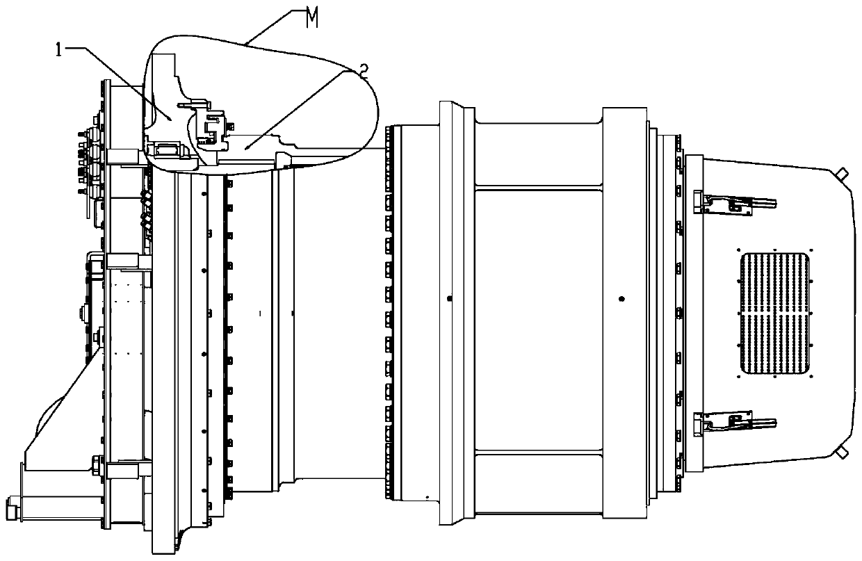
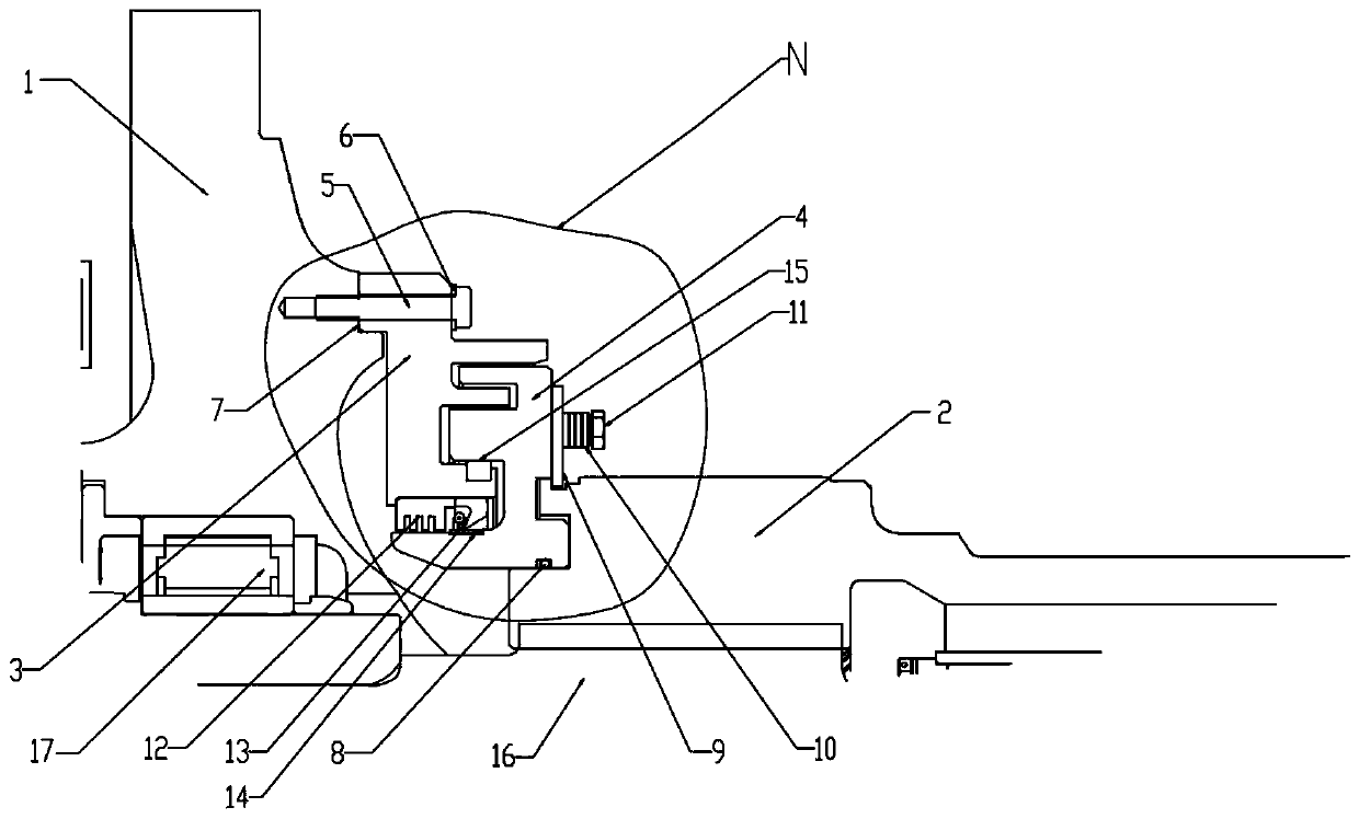
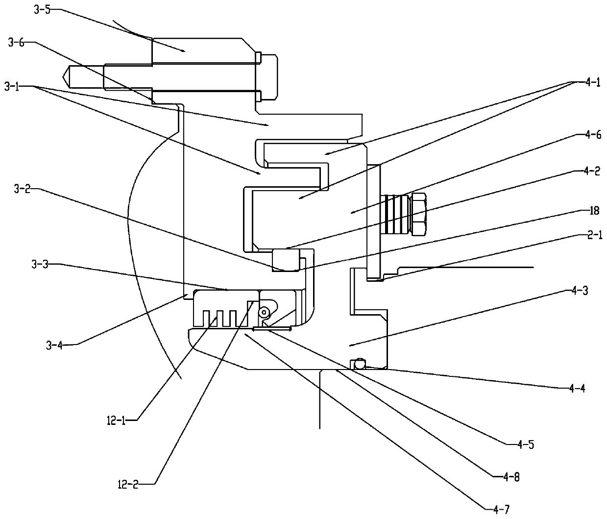
[0019] The combined sealing structure of the wheel reducer in this embodiment is applied in figure 1 The torque output end of the mine wheel side reducer shown is between the frame 1 connected with the rear axle of the vehicle and the torsion shaft 2 connected with the tires of the vehicle. The stationary ring 3 and the moving ring 4 are respectively fixed at the opposite positions of the frame 1 and the torsion shaft 2, specifically as figure 2 and image 3 As shown, the buckle edge 3-5 of the static ring 3 is assembled and fixed with the frame 1 of the wheel reducer through the static ring mounting bolt 5 and the anti-loosening gasket 6, and the inner stop of the buckle edge 3-5 is connected with the frame 1 The transition fit of the outer seam on the top, the assembly surface 3-6 of the static ring 3 and the frame 1—including the end surface and the seam mating surface are coated with end face sealant 7, which is used to prevent lubricating oil from the assembly surface 3...


PUM


Abstract

The invention relates to a hub reduction gear combined sealing structure, and belongs to the technical field of vehicle transmission. The sealing structure comprises a static ring and a movable ring,wherein the static ring is fixed to a frame; the movable ring is opposite to the static ring, and is fixedly connected to a torsion shaft; the end face of the static ring is provided with at least three rings from outside to inside along the radial direction; the outer circle of the ring on the innermost layer is provided with a clamping groove embedded with a packing; the inner circle of the ringon the innermost layer is in tight fit with a throttling ring and a framework oil seal; the throttling ring is provided with a group of radial extension combs which are arranged at intervals along the axial direction; the end face of the movable ring is provided with a circular lug and a lower edge inner ring which are embedded between adjacent rings to construct a radial labyrinth seal from outside to inside along the radial direction; the inner circumferential surface, opposite to the clamping groove, of the circular lug is in contact with the packing to construct a packing seal; the outercircle of the lower edge inner ring is in contact with the framework oil seal to seal the framework oil seal; and a throttling ring seal is formed at a position opposite to the throttling ring. The quadruple sealing structures perform own functions. Through organic combination, the lip edge of the framework oil seal is always in a stable and reliable sealing state, so that the fatigue failure is avoided effectively, and oil leakage after long-term use is avoided.

Description

technical field [0001] The invention relates to a combined sealing structure, in particular to a combined sealing structure of a wheel-side reducer, which belongs to the technical field of vehicle transmission. Background technique [0002] According to the applicant's knowledge, the drive tires of vehicles such as electric transmission mining dump trucks in mining and other industries are equipped with wheel-side reducers, which are used to bear the weight of the entire vehicle distributed on the rear axle and transmit torque to drive the mining dump truck. Since a certain amount of lubricating oil is injected inside the wheel reducer to lubricate internal gears and bearings and other components, it is necessary to use the static seal at the power input end and the dynamic seal device at the power output end to isolate from the outside world to achieve reliable sealing. [0003] However, the power output end is directly in contact with the atmosphere above the wheel surface...

Claims


Application Information

Patent Timeline
IPC IPC(8): F16H57/029
CPCF16H57/029F16H2057/02043
Inventor 段振中张再利徐莎汪星王伟康
Owner CRRC QISHUYAN INSTITUTE CO LTD
Why Eureka
Try Eureka