Gearbox for spraying machine

A gearbox and sprayer technology, applied in the direction of mechanical equipment, gear transmission, transmission control, etc., can solve the problems of gearbox usage restrictions, inconvenient lubrication of parts, and unsatisfactory parts, and achieve a wide range of output torque and speed , The structure and assembly process are simple, and the effect of reducing the assembly connection space

Inactive Publication Date: 2019-11-29
青州上力机械科技有限公司
View PDF0 Cites 0 Cited by
  • Summary
  • Abstract
  • Description
  • Claims
  • Application Information

AI Technical Summary

Problems solved by technology

[0003] 1. The internal structure and transmission relationship of the gearbox of the existing sprayer are complicated, and the output torque and speed range of the gearbox are narrow, which cannot meet the needs of different working conditions of walking and working
[0004] 2. The size of the gearbox is large, the installation is inconvenient, and the applicability is poor
[0005] 3. Only one output shaft, single function, narrow scope of application
[0006] 4. In the prior art, the gearbox is connected to the engine through the connecting flange and the connecting transmission shaft, which is noisy and takes up a lot of space for assembly and installation. The use of the gearbox is limited, so that the layout of the whole vehicle is not compact enough.
[0007] 5. It is inconvenient to lubricate the upper part of the gearbox, the lubrication effect is poor, and the service life of the parts is short
[0008] 6. The internal structure of the gearbox is complicated, the number of parts is large, and the versatility of the parts is poor, the assembly process is complicated and the cost is high
[0009] 7. The operation of shifting gears is complicated. The position of the shaft gear is changed by the gear lever to achieve the meshing and separation of different gears, and the change of the gear position is realized. The frictional resistance is large; during the gear shifting operation, the gearbox operation is time-consuming and laborious, and the position of the gear lever limits the speed change box installation location
[0010] In summary, there are obviously inconveniences and defects in the actual use of the existing technology, so it is necessary to improve

Method used


Image

  • Gearbox for spraying machine
  • Gearbox for spraying machine
  • Gearbox for spraying machine

Examples


Embodiment 1

[0047]Embodiment 1 A kind of gearbox for sprayer

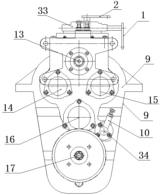
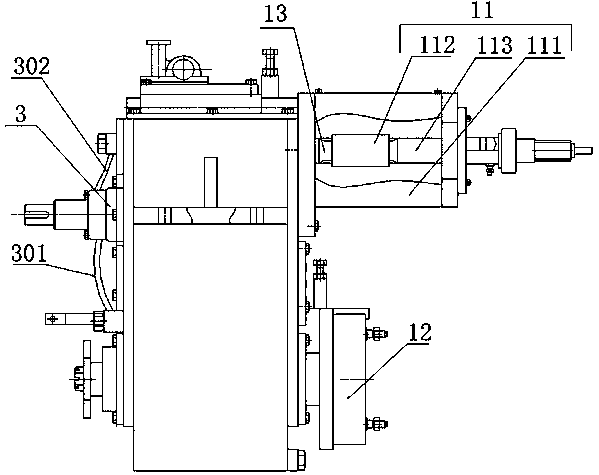
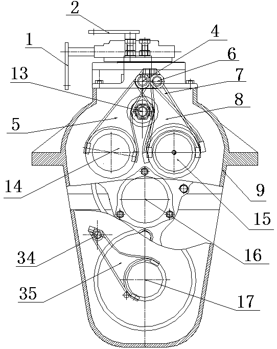
[0048] Such as Figure 1-5 As shown, the present invention provides a gearbox for a sprayer, including a casing 9, a power input shaft 13, a third transmission shaft 16 and a power output shaft 17 are arranged from top to bottom in the casing 9, and the power The input shaft 13, the third transmission shaft 16 and the power output shaft 17 are arranged facing up and down; the first transmission shaft 14 and the second transmission shaft 15 which are symmetrical to each other are arranged between the power input shaft 13 and the third transmission shaft 16; The first transmission shaft 14 and the second transmission shaft 15 are arranged on the same level.

[0049] The power input shaft 13 , the first transmission shaft 14 , the second transmission shaft 15 , the third transmission shaft 16 and the power output shaft 17 are all rotatably connected to the side wall of the box body 9 through bearings 18 .

[0050] The input end...


PUM


Abstract

The invention discloses a gearbox for a spraying machine. The gearbox comprises a box body which is internally provided with a power input shaft, a first transmission shaft, a second transmission shaft, a third transmission shaft and a power output shaft; the power output shaft is fixedly provided with a first gear; the first transmission shaft is provided with a second gear, a reverse sliding sleeve and a reverse gear; the second transmission shaft is provided with a third gear, a fourth gear, a second sliding sleeve, a fifth gear, a first sliding sleeve and a sixth gear; the third transmission shaft is fixedly provided with a ninth gear, a eighth gear and a seventh gear; and the power output shaft is slidably provided with a duplex gear. The gearbox can meet the walking condition and theworking condition and is good in applicability, and application of the gearbox can be wider; the structure of the gearbox is compact, and noise is low; the gearbox can achieve self lubrication, and the part universality of the gearbox can be improved; and the gearbox can achieve gear engaging operation easily, gear disengagement is not prone to occurring, and the gearbox can achieve gear engagingthrough a flexible shaft.

Description

technical field [0001] The invention relates to a gearbox, in particular to a gearbox for a sprayer, which belongs to the technical field of gearboxes for rural plant protection machinery, and can also be used for other small agricultural and construction machinery such as seedling transporters and road rollers. Background technique [0002] The gearbox of the existing sprayer is generally a gearbox for a small loader or a road roller. In practical applications, the gearbox has the following technical defects: [0003] 1. The internal structure and transmission relationship of the gearbox of the existing sprayer are complicated, and the output torque and speed range of the gearbox are narrow, which cannot meet the needs of different working conditions of walking and working. [0004] 2. The gearbox is large in size, inconvenient to install and poor in applicability. [0005] 3. There is only one output shaft with single function and narrow application range. [0006] 4. In...

Claims


Application Information

Patent Timeline
Patent Type & Authority Applications(China)
IPC IPC(8): F16H3/20F16H57/023F16H57/04F16H63/30
CPCF16H3/20F16H57/023F16H57/0436F16H63/30
Inventor 张海军张海源
Owner 青州上力机械科技有限公司
Why Eureka
Try Eureka