Small-sized thin-wall non-magnetic workpiece positioning and clamping device suitable for automatic production line

An automatic production line, positioning and clamping technology, applied in positioning devices, metal processing machinery parts, clamping, etc., can solve problems such as poor positioning accuracy, health hazards of workers, and high risk factor of work, so as to achieve low machining interference Effect

Pending Publication Date: 2019-11-29
NINGBO INST OF TECH ZHEJIANG UNIV ZHEJIANG
View PDF0 Cites 0 Cited by
  • Summary
  • Abstract
  • Description
  • Claims
  • Application Information

AI Technical Summary

Problems solved by technology

However, the pneumatic method of clamping workpieces is only suitable for some small-load operations such as handling workpieces. If the workpiece requires a relatively heavy-load process, such as grinding, polishing, etc., the pneumatic clamping method cannot guarantee the stability of the clamping.
Moreover, the contact parts between the pneumatic components and the workpiece are generally made of materials that are easy to deform to adapt to the change of the shape of the workpiece, which will inevitably cause a certain deformation during the clamping process. This deformation is difficult to accurately express online mathematically, which will lead to positioning poor precision
At the same time, the pneumatic method requires good sealing. If more debris enters the pneumatic system during workpiece processing, it will affect the normal operation of the pneumatic system.
[0003] Therefore, the above-mentioned workpieces cannot be processed by robots on the automatic assembly line because they cannot be clamped during processing. Health hazards for workers

Method used


Image

  • Small-sized thin-wall non-magnetic workpiece positioning and clamping device suitable for automatic production line
  • Small-sized thin-wall non-magnetic workpiece positioning and clamping device suitable for automatic production line
  • Small-sized thin-wall non-magnetic workpiece positioning and clamping device suitable for automatic production line

Examples


Embodiment approach

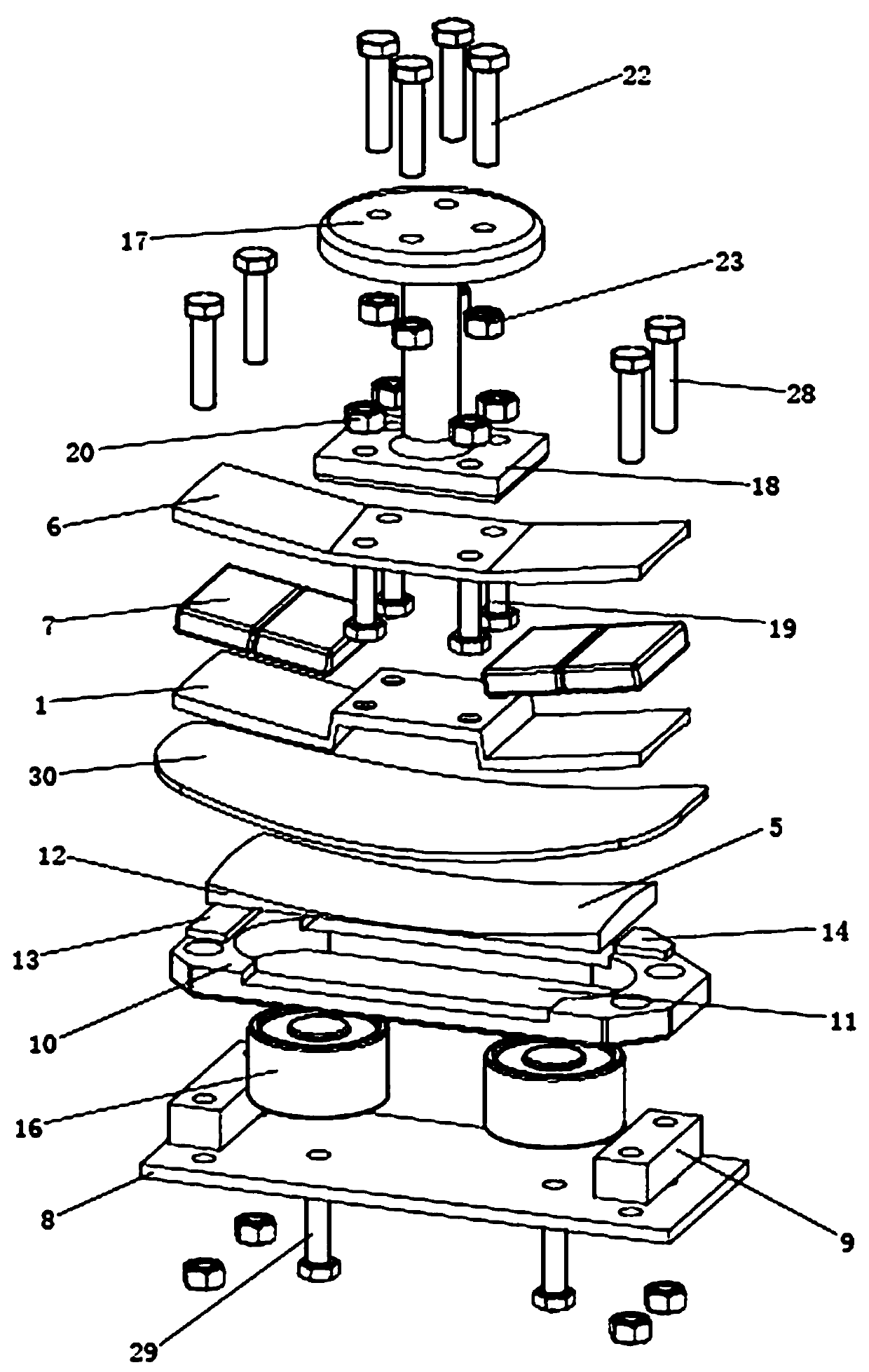
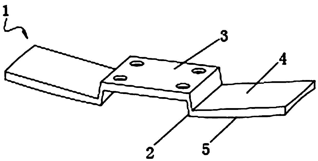
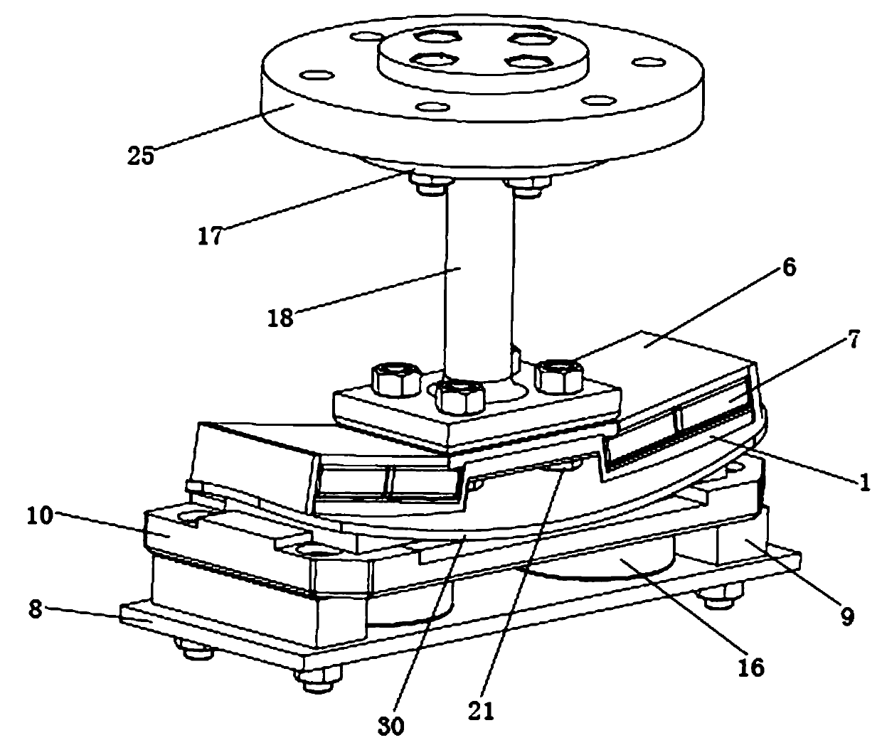
[0071] In order to increase the frictional force of the second magnetically conductive clamping plate 12 on the workpiece 30 when the workpiece 30 is processed, and improve the stability of the clamping device; the second embodiment of the present invention, such as Figure 5 As shown, a workpiece positioning and clamping device in this embodiment, the lower die set in its structure also includes an anti-slip pad 31 with a relatively large friction coefficient with respect to the material of the workpiece 30, and the anti-slip pad 31 is closely attached to On the second workpiece clamping curved surface 15 of the second magnetic conduction clamping plate 12, and both are fixed. In this embodiment, the anti-slip gasket 31 is made of silica gel with a high friction coefficient.

[0072] In order to make the lower mold group can rotate freely in a certain angle range in the vertical direction, the workpiece 30 above can be placed on the positioning table 10 through various geomet...


PUM


Abstract

The invention relates to a workpiece positioning and clamping device suitable for an automatic production line, in particular to a small-sized thin-wall non-magnetic workpiece positioning and clampingdevice suitable for an automatic production line. The small-sized thin-wall non-magnetic workpiece positioning and clamping device comprises an upper module and at least one lower module. The upper module moves in the posture required by workpiece clamping under the driving of a robot to a workpiece clamping station, and workpieces to be machined on the lower modules are clamped under the magnetic force action. The lower modules position the workpieces, and all the lower modules are installed on a workpiece conveying system and fall on the workpiece clamping station one by one under the driving of the workpiece conveying system. The lower modules located on the workpiece clamping station complete the clamp-unloading of the machined workpieces on the upper module under the magnetic force action. The workpiece positioning and clamping device has the beneficial effects that the problems of positioning and clamping of small-thin workpieces are solved in the machining operation process ofremoving burrs on the peripheries of the small-thin workpieces, and the productivity of the automatic production line of the robot can be remarkably improved.

Description

technical field [0001] The invention relates to a workpiece positioning and clamping device suitable for an automatic production line, in particular to a small thin-walled non-magnetic workpiece positioning and clamping device suitable for an automatic production line. Background technique [0002] At present, manufacturing enterprises generally use pneumatic clamping for small thin-walled non-magnetic workpieces, especially irregular-shaped workpieces, such as small pieces of stainless steel, ceramics, and plastics. However, the pneumatic method of clamping workpieces is only suitable for some small-load operations such as handling workpieces. If the workpiece needs to undergo a relatively heavy-load process, such as grinding, polishing, etc., the pneumatic clamping method cannot guarantee the stability of the clamping. Moreover, the contact parts between the pneumatic components and the workpiece are generally made of materials that are easy to deform to adapt to the chang...

Claims


Application Information

Patent Timeline
Patent Type & Authority Applications(China)
IPC IPC(8): B23Q3/06
CPCB23Q3/065
Inventor 詹建明陈彪周杰胡利永王义强张慧娟
Owner NINGBO INST OF TECH ZHEJIANG UNIV ZHEJIANG
Why Eureka
Try Eureka