
Inner hole direct grinding machine chuck mechanism capable of centralized positioning

A center-positioning, straight-grinding technology, applied in machine tools, grinding machines, and parts of grinding machine tools designed for grinding the rotating surface of workpieces, etc. Problems such as poor axiality and poor grinding accuracy can achieve the effects of easy adjustment, good uniformity and coaxiality, and convenient control.

Active Publication Date: 2019-11-26
温州市瑞基科技有限公司
View PDF5 Cites 4 Cited by
  • Summary
  • Abstract
  • Description
  • Claims
  • Application Information

AI Technical Summary

Problems solved by technology

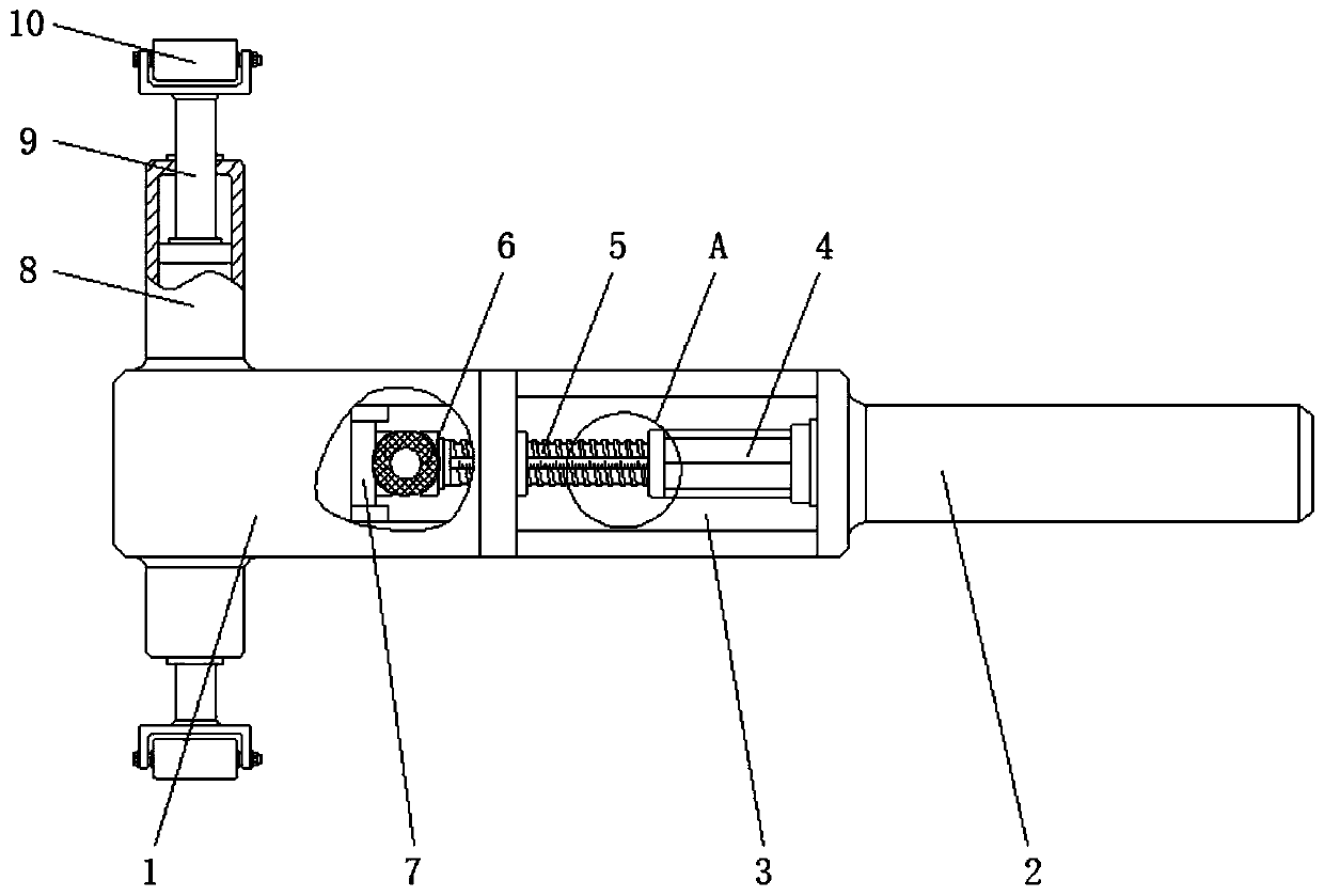
[0005] The present invention provides a centrally positioned inner hole straight grinder chuck mechanism, which has the advantages of good uniformity and coaxiality of the hole wall after grinding, high grinding accuracy, easy adjustment, and convenient operation, and solves the problem of In the process of grinding the inner hole of the existing straight grinder, the center cannot be effectively positioned, and the assembly personnel can only rely on the hand-held straight grinder to tighten the hole wall and carry out the grinding operation, which is difficult to control, and this kind of grinding The method belongs to a segmented grinding, which makes it impossible to accurately control the grinding depth of the inner hole, which eventually leads to poor uniformity and coaxiality of the hole wall after grinding, and poor grinding accuracy.

Method used


Image

  • Inner hole direct grinding machine chuck mechanism capable of centralized positioning
  • Inner hole direct grinding machine chuck mechanism capable of centralized positioning
  • Inner hole direct grinding machine chuck mechanism capable of centralized positioning

Examples


Embodiment Construction

[0020] The following will clearly and completely describe the technical solutions in the embodiments of the present invention with reference to the accompanying drawings in the embodiments of the present invention. Obviously, the described embodiments are only some, not all, embodiments of the present invention. Based on the embodiments of the present invention, all other embodiments obtained by persons of ordinary skill in the art without making creative efforts belong to the protection scope of the present invention.

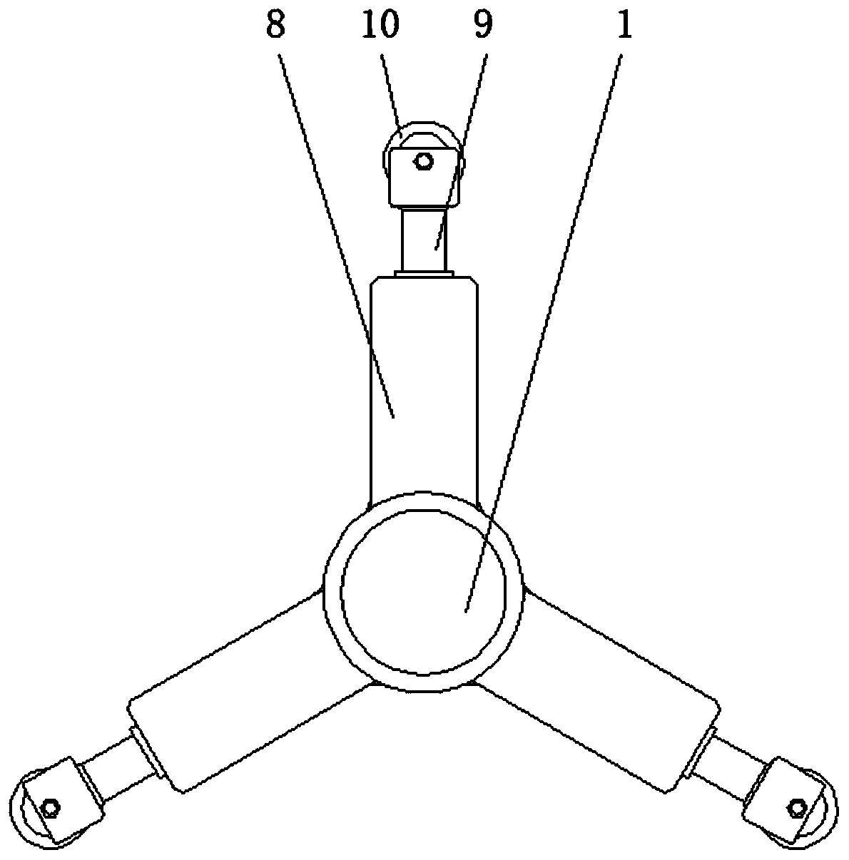
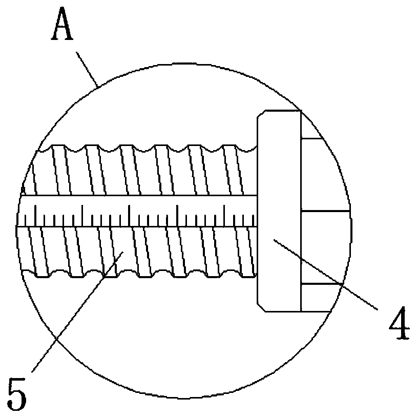
[0021] see Figure 1-3 , a centrally positioned inner hole straight grinder chuck mechanism, including a positioning sleeve 1, a clamping link 2 is fixedly installed on the outside right side of the positioning sleeve 1, and an adjusting rod is installed on one side of the positioning sleeve 1. Cavity 3, and one side of the inside of the adjustment cavity 3 is movably sleeved with an adjustment sleeve 4, and the inner thread of the adjustment sleeve 4 is conne...


PUM


Abstract

The invention relates to the technical field of mechanical machining and assembling, and discloses an inner hole direct grinding machine chuck mechanism capable of centralized positioning. The mechanism comprises a positioning sleeve, wherein a clamping connecting rod is fixedly installed on the right side outside the positioning sleeve, an adjusting cavity is formed in one side inside the positioning sleeve, an adjusting sleeve is movably sleeved with one side inside the adjusting cavity, an adjusting screw rod is in threaded connection with the inside of the adjusting sleeve, and one end ofthe adjusting screw rod penetrates through and extends into the positioning sleeve and is in transmission connection with a piston located on the inner wall of the positioning sleeve through a pressure ball. According to the inner hole direct grinding machine chuck mechanism capable of centralized positioning, through the arrangement of the adjusting sleeve, the adjusting screw rod and the pressure ball, the energy storage can be carried out on the pressure ball in advance, so that the grinding depth of grinding wheels is adjusted in advance; and compared with an existing direct grinding machine, the working mode of grinding while adjusting the grinding depth manually is not needed, meanwhile, the stresses between the three sets of grinding wheels are equal, so that the grinding precisionof the chuck mechanism is further improved.

Description

technical field [0001] The invention relates to the technical field of mechanical processing and assembly, in particular to a centrally positioned inner hole straight grinder chuck mechanism. Background technique [0002] Mechanical assembly is a labor process in which several parts or components are combined and spliced ​​into a complete product according to the specified technical requirements. In the process of assembly, the cooperation between shaft parts and holes is a common assembly structure, but the processing of inner holes is due to Due to factors such as processing conditions, materials and external temperature environment, there will be a certain accuracy error in the inner hole structure after processing, which will cause the shaft parts to fail to meet the assembly requirements. [0003] Therefore, in the process of assembly work, straight grinders are often used to grind the inner holes to a certain extent, but the existing straight grinders cannot effectivel...

Claims


Application Information

Patent Timeline
Patent Type & Authority Applications(China)
IPC IPC(8): B24B5/06B24B5/48B24B27/00B24B41/00B24B41/04
CPCB24B5/06B24B5/48B24B27/0076B24B41/007B24B41/04
Inventor 潘凤春
Owner 温州市瑞基科技有限公司
Learn More