Cam confirming device when camshaft is press-fitted

A technology for confirming devices and camshafts, applied in metal processing equipment, metal processing, manufacturing tools, etc., can solve the problems of unqualified press-fitting and low press-fitting efficiency, and achieve higher press-fitting pass rate and high accuracy of orientation determination , to meet the effect of high-efficiency assembly line

Active Publication Date: 2020-09-01
重庆九方铸造有限责任公司
View PDF7 Cites 0 Cited by
  • Summary
  • Abstract
  • Description
  • Claims
  • Application Information

AI Technical Summary

Problems solved by technology

[0004] The main purpose of the present invention is to provide a cam confirmation device for camshaft press-fitting, which can better confirm the orientation of the cam to the direction required for press-fitting, and solve the problems of low press-fitting efficiency and unqualified press-fitting in the prior art

Method used


Image

  • Cam confirming device when camshaft is press-fitted
  • Cam confirming device when camshaft is press-fitted
  • Cam confirming device when camshaft is press-fitted

Examples


Embodiment 1

[0033] Embodiment 1 is basically as follows:

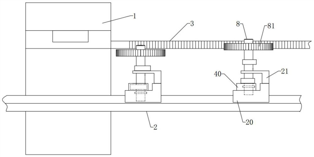
[0034] Cam confirming device when camshaft is press-fitted, such as figure 1 As shown, it includes the transmission mechanism 2 passing through the pressing machine 1. The transmission mechanism 2 in this embodiment specifically selects a chain conveyor belt, and the chain conveyor belt is fixedly connected with a moving seat 20 by bolts; The moving base 20 is slidably connected with the guide rail, and a motor driving mechanism for driving the moving base 20 to move toward the direction of the rail needs to be set on the moving base 20 . The movement of the moving seat 20 can send the camshaft 8 into the press-fitting machine 1 .

[0035] The top of the transmission mechanism 2 is provided with a rack 3 fixed to the press machine 1, and the rack 3 is parallel to the transmission direction of the transmission mechanism 2. When the camshaft 8 is transported by the moving seat 20, the gear plate 81 on the camshaft 8 is aligned wit...

Embodiment 2

[0042] The difference from Embodiment 1 is that, as Figure 5 As shown, the opening groove 23 has a matching portion matching the shape of the cam I82. The orientations of the cams I 82 on the camshaft 8 are perpendicular to each other, and the matching portion of the opening groove 23 can be used to cooperate with the cam I 82 that is closer to the gear plate 81 . In this way, the cam II 83 and the cam I 82 on the camshaft 8 are respectively aligned with the fitting groove 41 of the clamping block 40 and the matching portion of the opening groove 23, and the camshaft 8 will fall downward, thereby improving the accuracy of determining the direction of the cam II 83 and the cam I 82. sex.

Embodiment 3

[0044] The difference from Embodiment 1 and Embodiment 2 is that, as Image 6 As mentioned above, wedge-shaped blocks 6 are welded and fixed on the two clamping plates, and two fixed blocks 7 that can offset the wedge-shaped blocks 6 are welded and fixed on the press machine 1. Compatible inclined surfaces.

[0045] The moving seat 20 moves toward the press machine 1 with the camshaft 8, and the wedge block 6 is opposed to the fixed block 7, and the fixed block 7 can push the clamping plates close to each other through the wedge block 6, thereby clamping and fixing the camshaft 8. Compared with Embodiment 1 and Embodiment 2, power equipment such as motors and cylinders are not used, thereby reducing the cost of the device and reducing the wiring requirements of the device.


PUM


Abstract

The invention belongs to the technical field of machining equipment, and particularly relates to a cam confirmation device during press mounting of a camshaft. The cam confirmation device comprises aconveying mechanism used for conveying the camshaft to a press-mounting machine, and the conveying mechanism is connected with a movable seat; the movable is slidably connected with two clamping blocks, and each clamping block is provided with a matching slot which can be coordinated with a cam; the movable seat is provided with a counter bore which can communicate with the matching slot and can be coordinated with a shaft lever; and a rack which is parallel with the conveying direction of the conveying mechanism and is fixed to the press-mounting machine is arranged above the conveying mechanism, and the rack can be engaged with a gear disk of the camshaft. According to the cam confirmation device, the orientation of the cam can be confirmed to the required direction for press mounting properly, and the problems of low press mounting efficiency and unqualified press mounting in the prior art are solved; and meanwhile the requirements of a high efficiency flow production line are met.

Description

technical field [0001] The invention relates to the technical field of mechanical processing equipment, and specifically designs a cam confirmation device when a camshaft is press-fitted. Background technique [0002] The camshaft is a part of a piston engine and is widely used in fuel vehicle engines, such as Figure 7 As mentioned above, the camshaft 8 includes a shaft 80, one end of the shaft 80 is connected with a gear plate 81, and the middle part is connected with a cam I 82 and a cam II 83. After the camshaft is poured and formed, after grinding, polishing, milling, drilling and other processes, the camshaft needs to be moved to the camshaft pressing machine to install the parts. Before installing the parts, it is necessary to confirm the orientation of the cam for accurate press fit. [0003] At present, the camshaft press-fitting operation is carried out by workers. The workers place the camshaft on the clamping seat on the press-fitting machine, adjust the orienta...

Claims


Application Information

Patent Timeline
Patent Type & Authority Patents(China)
IPC IPC(8): B23P19/02
CPCB23P19/002B23P19/006B23P19/02
Inventor 张筱川
Owner 重庆九方铸造有限责任公司
Why Eureka
Try Eureka